| Line 81: | Line 81: | ||
==Alternate Solution== | ==Alternate Solution== | ||
| + | The above filter does attenuate the desired frequencies, but it also attenuates any frequencies lower than 235Hz. This can be somewhat remedied by adding a pole to the filter. Using the same values as above, we will add a single, all-real pole to the filter. Our transfrer function is then | ||
| + | |||
| + | <math>\begin{align} | ||
| + | \text{H} (z) &= \frac{(1-re^{j\theta}z^{-1})(1-re^{-j\theta}z^{-1})}{1-r_p z^{-1}} \\ | ||
| + | &= \frac{1 - 2r\text{cos}(\theta)z^{-1} + r^2z^{-2}}{1-r_p z^{-1}} | ||
| + | \end{align}</math> | ||
| + | |||
| + | The value for r_p is chosen so that the gain at w=0 will be comparable to the gain at w=pi. By trial-and-error, r_p=0.982. The transfer function is then | ||
| + | |||
| + | <math>\begin{align} | ||
| + | \text{H} (z) &= \frac{1 - 2(0.95)\text{cos}(0.185)z^{-1} + 0.95^2z^{-2}}{1-0.982 z^{-1}} \\ | ||
| + | &= \frac{1 -1.87 z^{-1}+0.9025z^{-2}}{1-0.982 z^{-1}} | ||
| + | \end{align}</math> | ||
| + | |||
| + | The pole-zero plot is shown below. | ||
| + | |||
| + | [[Image:ECE438F14_HW9_TwoZero_addedPoleZPlot.png]] | ||
---- | ---- | ||
Revision as of 08:55, 20 November 2014
Contents
Homework 9, ECE438, Fall 2014, Prof. Boutin
Question Statement
Obtain the transfer function of a system that attenuates the sound of vuvuzelas in the digital recording of a soccer match commentary.
a) Write the expression for the transfer function of your system. (Do not forget to specify the ROC.)
b) Is the frequency response of your system well defined? If so, what is it? If not, explain why it is not well defined.
c) Obtain the difference equation describing the relationship between the output of the system y[n] and the input of the system x[n]. (Show how to obtain this relationship from the transfer function of the system.)
Solution
First, a few numbers that are needed for this problem. Let
$ f_v = 235 \text{Hz, the frequency of the vuvuzela} $ $ f_s = 8 \text{kHz, the sampling frequency} $
You could have chosen a different sampling frequency. One good choice would be 44.1kHz (the standard sampling rate for CD's).
a) Write an expression for the transfer function.
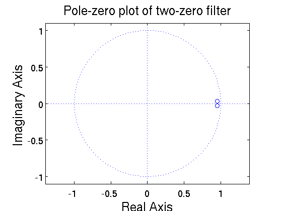
For simplicity, this filter will be a two zero filter, using complex conjugates. The Z-transform of this filter is
$ \begin{align} \text{H}(z) &= (1-re^{j\theta}z^{-1})(1-re^{-j\theta}z^{-1}) \\ &= 1 - 2r\text{cos}(\theta)z^{-1} + r^2z^{-2} \end{align} $
The value r is chosen by the designer of the filter. It should not equal 1 (directly on the unit circle) because there is some true signal at the same frequency as the vuvuzelas. For this filter, it will be r=0.95. Theta is calculated as
$ \theta = \frac{f_v}{f_s}2\pi = \frac{235}{8000}2\pi = 0.185 $
The transfer function is then
$ \begin{align} \text{H}(z) &= 1 - 2(0.95)cos(0.185)z^{-1} + 0.95^2z^{-2} \\ &= 1 -1.87 z^{-1}+0.9025z^{-2} \mbox{, ROC: everywhere except } z=0 \end{align} $
The pole-zero plot is shown below.
b) Is the frequency response of your system well defined? If so, what is it? If not, explain why it is not well defined.
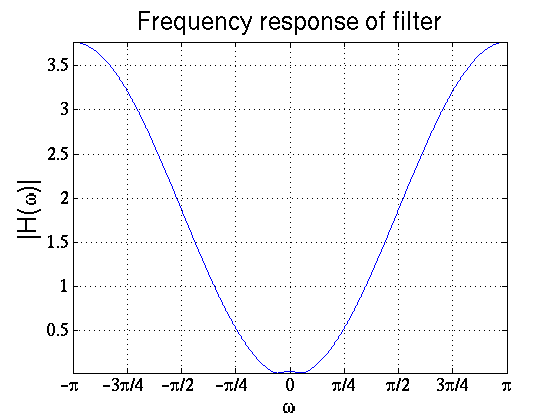
The ROC includes the unit circle, so the frequency response is well defined. The frequency response is
$ \begin{align} \text{H} (\omega) = \text{H}(z)|_{z=e^{j\omega}} = 1 -1.87 e^{-j\omega}+0.9025e^{-j2\omega} \end{align} $
Below is a plot of the frequency response of the filter.
c) Obtain the difference equation describing the relationship between the output of the system y[n] and the input of the system x[n]. (Show how to obtain this relationship from the transfer function of the system.)
From the transfer function:
$ \text{H}(z) = \frac{\text{Y}(z)}{\text{X}(z)} = 1 -1.87 z^{-1}+0.9025z^{-2} $ $ \text{Y}(z) = X(z)(1 -1.87 z^{-1}+0.9025z^{-2}) $
Using the time-shift property of the Z-transform
$ x(n-k) \leftrightarrow z^{-k}\text{X}(z) $
we see that the difference equation for the given filter is
$ y[n] = x[n] - 1.87x[n-1] + 0.9025 x[n-2] $
Alternate Solution
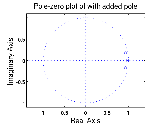
The above filter does attenuate the desired frequencies, but it also attenuates any frequencies lower than 235Hz. This can be somewhat remedied by adding a pole to the filter. Using the same values as above, we will add a single, all-real pole to the filter. Our transfrer function is then
$ \begin{align} \text{H} (z) &= \frac{(1-re^{j\theta}z^{-1})(1-re^{-j\theta}z^{-1})}{1-r_p z^{-1}} \\ &= \frac{1 - 2r\text{cos}(\theta)z^{-1} + r^2z^{-2}}{1-r_p z^{-1}} \end{align} $
The value for r_p is chosen so that the gain at w=0 will be comparable to the gain at w=pi. By trial-and-error, r_p=0.982. The transfer function is then
$ \begin{align} \text{H} (z) &= \frac{1 - 2(0.95)\text{cos}(0.185)z^{-1} + 0.95^2z^{-2}}{1-0.982 z^{-1}} \\ &= \frac{1 -1.87 z^{-1}+0.9025z^{-2}}{1-0.982 z^{-1}} \end{align} $
The pole-zero plot is shown below.
Discussion
You may discuss the homework below.
- write comment/question here
- answer will go here


