Line 339: Line 339:
 
<br>
 
<br>
 
Looked at an example PWM program for the micro and looked up information in the datasheet. PWM mode can be chosen for each channel in each of the four timers. This is selected by setting the TIMx_CCMRx register correctly.In PWM mode (1 or 2), TIMx_CNT and TIMx_CCRx are always compared to determine whether TIMx_CCRx≤ TIMx_CNT or TIMx_CNT≤ TIMx_CCRx (depending on the direction of the counter). The duty cycle can be adjusted with the TIMx_CCRx registers. I tried to combine the PWM initialization code with ADC initialization code and LCD code to control the CCR register with the ADC value, but have not gotten it to work yet. Thus the code used manually controlled the the PWM at a specific frequency and duty cycle.<br><br>
 
Looked at an example PWM program for the micro and looked up information in the datasheet. PWM mode can be chosen for each channel in each of the four timers. This is selected by setting the TIMx_CCMRx register correctly.In PWM mode (1 or 2), TIMx_CNT and TIMx_CCRx are always compared to determine whether TIMx_CCRx≤ TIMx_CNT or TIMx_CNT≤ TIMx_CCRx (depending on the direction of the counter). The duty cycle can be adjusted with the TIMx_CCRx registers. I tried to combine the PWM initialization code with ADC initialization code and LCD code to control the CCR register with the ADC value, but have not gotten it to work yet. Thus the code used manually controlled the the PWM at a specific frequency and duty cycle.<br><br>
I tried our circuit again for PWM motor speed control, and after an hour or two when the rest of the group came we figured out that the 2N3704 NPN BJT we were using was being fried by the collector to emitter voltage/current. We found this out when we noticed one became burning hot and did not operate correctly. Scott and I went to radio shack and got two TIP 120s (Darlington BJT). We rebuilt the circuit but the motor was still not responding to the PWM input. After probing the circuit we found the the 5V output from the microcontroller was not functioning correctly.  
+
I tried our circuit again for PWM motor speed control, and after an hour or two when the rest of the group came we figured out that the 2N3704 NPN BJT we were using was being fried by the collector to emitter voltage/current. We found this out when we noticed one became burning hot and did not operate correctly. Scott and I went to radio shack and got two TIP 120s (Darlington BJT). We rebuilt the circuit but the motor was still not responding to the PWM input. After probing the circuit we found the the 5V output from the microcontroller was not functioning correctly. We used the Agilent E3631A DC PSU to supply 5V to the rail and the motor finally responded to the PWM output.
 
</td>
 
</td>
 
</tr>
 
</tr>

Revision as of 10:11, 4 November 2011

Jason Holmes - Design Notebook

Week of Sept. 19

September 21, 2011 (1.5 hours):
Participated in teleconference with HKUST. The discussion included possible processor options as well as the general scope of the project. Also received the new usernames for the HKUST students created for the Rhea page - emailed them to the team members.

September 22, 2011 (20 minutes):
Updated the Rhea page with information about the teleconference for those who were not there.

September 23, 2011 (1 hour):
Attended weekly meeting with VIP group.


WEEK SUMMARY:

Accomplishments: Obtained usernames for HKUST members
Weekly Work Total: 2.7 hours
Project Work Total: 2.7 hours


Week of Sept. 26

September 27, 2011 (45 minutes):
Researched processors and wireless modules, updated brainstorming session on the Rhea page. Still a little unsure of what I think.

September 27, 2011 (30 minutes):
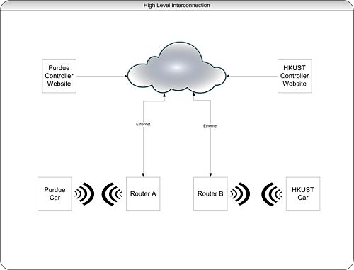
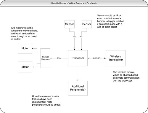
Created a whenisgood address to organize a group meeting to create a diagram of the desired system before our group meeting on Friday. Set meeting time after results from team members came in.

September 28, 2011 (1 hour):
Met with group members to create system diagram and discuss processor choice.

September 29, 2011 (45 minutes):
Finalized system diagram and did more research on a processor/development board.

High Level.jpg
Low Level.jpg

September 30, 2011 (1.5 hour):
Attended weekly VIP group meeting. Updated block diagrams to reflect discussions at the meeting and updated the Rhea page with notes from the meeting.


WEEK SUMMARY:

Accomplishments: Completed preliminary block diagram layout of system. Decided on potential processor family.
Weekly Work Total: 4.5
Project Work Total: 7.2


Week of Oct. 3

October 6, 2011 (2 hours):
Attended group meeting to design initial draft of poster for VIP poster session. Finished initial draft of poster at home and posted a pdf version to the Rhea site to be reviewed at Friday's meeting. Link here : Poster

October 7, 2011 (1 hour):
Revised poster based on Dr. Johnson's initial impressions and researched wireless transceivers.

October 7, 2011 (1.5 hours):
Attended weekly group meeting and updated Rhea page with meeting minutes.


WEEK SUMMARY:

Accomplishments: Finished poster for VIP poster session
Weekly Work Total: 4.5 hours
Project Work Total: 11.7 hours


Week of Oct. 10

October 11, 2011 (30 minutes):
Reformatted and submitted poster to be printed.

October 13, 2011 (1 hour):
Did research on development boards presented on Friday's meeting.

October 14, 2011 (1.5 hours):
Attended weekly meeting. Picked up development board!


WEEK SUMMARY:

Accomplishments: Decided on a development board to begin prototyping.
Weekly Work Total: 3 hours
Project Work Total: 14.7 hours


Week of Oct. 17

October 17, 2011 (30 minutes):
Updated Rhea page with Oct. 14 meeting minutes

October 17, 2011 (1 hour):
Got "Blinky" to run using KEIL software!

Blinky

October 18, 2011 (3 hours):
Attended scheduled meeting to decide on project parameters.
Vehicle Platform: Airsoft RC Electric Panzer Giant BattleTank

  • This vehicle was chosen because of its size and peripherals. It has plenty of room with a size of 2.5ft x 1ft.
  • It also has a moving turret already which is perfect for mounting a camera. In addition, the tank fires air soft pellets! This control can be investigated and added to the specs for the control of our vehicle if we want it to be able to fire.
  • We were concerned with the speed of the R/C cars of equivalent size - a lot of them up to 60mph. In addition, their cost was ~$150 and we are anticipating having to buy 2 to compensate for tearing one apart. At such a high speed, sensors to increase the autonomy of the vehicle would be virtually useless.


Wireless Module: RN-XV module

  • This module was simply chosen because of price and because it communicates through UART which is available for the Cortex-M3

IP Camera:TRENDnet TV-IP110WN Wireless N Internet Camera

  • It was very hard to find an appropriate IP camera. We wanted to find a camera that didn't depend on software. This camera is on the lower end of prices (hundreds were looked at) and it should work great.
  • All IP cameras have to be assigned a static IP address. This will need to be an option on the controlling website. Even if the camera was integrated, an IP update on the vehicle would still have to occur.


IR sensors and pushbuttons were chosen based on price. There is no need for long rang IR sensors.

October 19, 2011 (2 hours):
I did more research on IP cameras as I felt very unsure of using one. Not only did I feel like using one would be lame, there were just too many problems to deal with. One major problem is that IP cameras require that you connect to them via Ethernet and set up a static IP address for them. This would be extremely inconvenient for our purposes as every change in location would require a manual change in the camera's IP address. Also, most IP cameras require that you use the manufacturers software to access them - usually with a login and password on a browser. With time I'm sure our group could hack this requirement, but that is not really something we would like to do. (Not to mention IP cameras run ~$90 for the cheaper models)

I found a $10 CMOS camera on SparkFun, and one of the comments stated that someone had success interfacing to it with a Cortex M3! This will cause a change in our wireless transceiver as the one we chose previously would not be able to handle the throughput needed. We will be able to use the same line of transceivers, we will just have to pay more. There are many other CMOS cameras that we can choose from and this will give us greater flexibility in terms of implementation. It will be much harder to deal with the video feed ourselves, but will surely be more rewarding in the end.

Also attended VIP poster session which went really well.

October 20, 2011 (1 hour):
Found a new wireless transceiver that can potentially handle the data rate for the video feed and has i2c and well as other interfaces. More details on this later as I dig into the datasheet. Also created groups that we will break up into for project development and updated all of my research on this page: Research


WEEK SUMMARY:

Accomplishments:
Weekly Work Total: 8.5 hours
Project Work Total: 23.2 hours


Week of Oct. 24

October 25, 2011 (3.2 hours):
Met with group to complete tasks discussed at Friday's meeting. Last week we decided against using an IP camera because of the limitations. This week we looked into the requirements of implementing our own camera module. Unfortunately, the math did not come out in our favor. IP cameras use MJPEG compression internally before outputting the video to the web - which natively streams the MJPEG format. If we did not implement our own compression:

(640 x 480 pixels) X (2 bytes per pixel) = 614,400 bytes per frame
(614,400 bytes per frame) X (20 frames per second) = 12.3 MB/s output = 98.3 Mbps output

All of the CMOS cameras output in a RGB format or similar - raw image data. For most cameras, this is 16 bits per pixel. Without doing our own compression, this image data would be impossible to send wirelessly. There is a library for C to convert RGB data to JPEG format, which then possibly be converted to MJPEG on the controller side. This could possibly be used on-board, but the speed would have to be tested.


October 28, 2011 (1.5 hours):
Attended weekly VIP meeting. Updated Rhea page with meeting minutes and created a Doodle poll for Video Conference #2 with HKUST.


WEEK SUMMARY:

Accomplishments:
Weekly Work Total: 4.7 hours
Project Work Total: 27.9 hours


Week of Oct. 31

November 1, 2011 (4.5 hours):
Group disassembled one tank and found out exactly how the controls work. The controller (left/right and up/down) are simply switches. There are 4 relays on the basic circuit board - two for each drive motor. One switches on to drive each motor forward, and one for backward, supplying the battery's voltage and current. The turret is controlled by a small motor connected to a large gear. We will definitely change this as it is hard to control.

I located enough information to drive a very slow PWM channel that switched one pin on and off. We then constructed a circuit to drive the motor. To be on the safe side, we decided to optically isolate the drive to the motor. We calculated the correct resistor values for the BJT we were using and did not get it to work. So we tried it without and still couldn't get it to drive the motor even though all calculations and measurements from the DMM pointed to it working. We called it a night. Pictures and calculations will follow once we retry on Thursday.

November 3, 2011 (7 hours):
Looked at an example PWM program for the micro and looked up information in the datasheet. PWM mode can be chosen for each channel in each of the four timers. This is selected by setting the TIMx_CCMRx register correctly.In PWM mode (1 or 2), TIMx_CNT and TIMx_CCRx are always compared to determine whether TIMx_CCRx≤ TIMx_CNT or TIMx_CNT≤ TIMx_CCRx (depending on the direction of the counter). The duty cycle can be adjusted with the TIMx_CCRx registers. I tried to combine the PWM initialization code with ADC initialization code and LCD code to control the CCR register with the ADC value, but have not gotten it to work yet. Thus the code used manually controlled the the PWM at a specific frequency and duty cycle.

I tried our circuit again for PWM motor speed control, and after an hour or two when the rest of the group came we figured out that the 2N3704 NPN BJT we were using was being fried by the collector to emitter voltage/current. We found this out when we noticed one became burning hot and did not operate correctly. Scott and I went to radio shack and got two TIP 120s (Darlington BJT). We rebuilt the circuit but the motor was still not responding to the PWM input. After probing the circuit we found the the 5V output from the microcontroller was not functioning correctly. We used the Agilent E3631A DC PSU to supply 5V to the rail and the motor finally responded to the PWM output.


WEEK SUMMARY:

Accomplishments:
Weekly Work Total: hours
Project Work Total: hours


Back to Design Notebooks

Alumni Liaison

Correspondence Chess Grandmaster and Purdue Alumni

Prof. Dan Fleetwood