(→AM modulation) |
(→AM modulation) |
||
| Line 15: | Line 15: | ||
[[Image:Modulation_ECE301Fall2008mboutin.gif]] | [[Image:Modulation_ECE301Fall2008mboutin.gif]] | ||
| + | |||
[[Image:hw92_ECE301Fall2008mboutin.jpg]] | [[Image:hw92_ECE301Fall2008mboutin.jpg]] | ||
Revision as of 17:44, 17 November 2008
AM modulation
Now we know that
$ x(t) $ ⇒ $ X(\omega) $
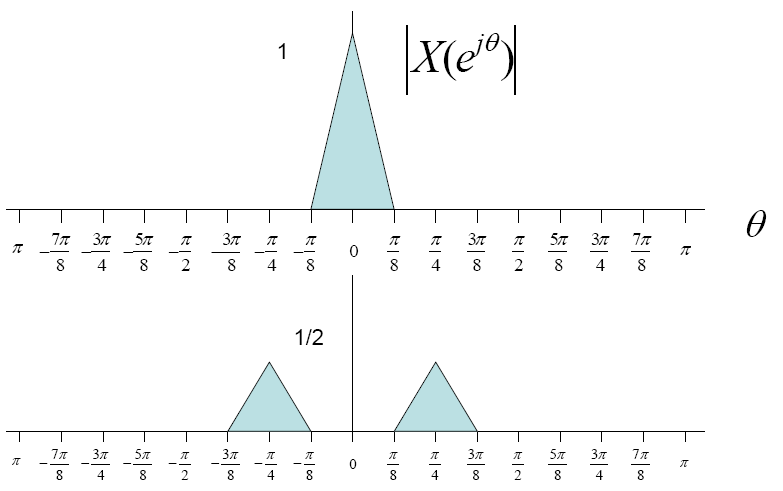
Now suppose the input signal was multiplied by a cosine wave
then the fourier transform of the wave would look as follows
$ x(t)*cos(\frac{\pi t}{4}) $ ⇒ $ \frac{1}{2}[X(e^{j(\theta - \pi/4)}) + X(e^{j(\theta + \pi/4)}) ] $.
In short we are getting two side bands which look something like this
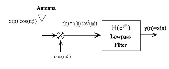
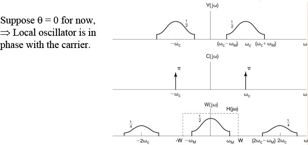
AM Demodulation
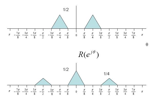
$ r(n)= x(n)cos^2(n \theta)= \frac{1}{2} x(n) + \frac{1}{2}x(n)cos(2n\theta) $
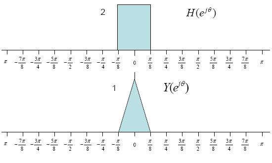
$ Y(e^{j\theta})= R(e^{j\theta})H(e^{j\theta}) $
$ = \frac{1}{2}X(e^{j\theta})+\frac{1}{4}X(e^{j\theta-2\phi})+\frac{1}{4}X(e^{j\theta+2\phi})H(e^{j\theta}) $
$ = X(e^{j\theta}) $

