| (12 intermediate revisions by the same user not shown) | |||
| Line 87: | Line 87: | ||
[[Image:z-transform of right sided signal.jpg|1000x1000px]]<br /> | [[Image:z-transform of right sided signal.jpg|1000x1000px]]<br /> | ||
| − | [ | + | [https://drive.google.com/open?id=0B4fZ7EOM05AwMGxmNWU2V1NjUWs Z-transform of Right Sided signal explanation]<br /> |
<big>2. Left Sided Signal <br /></big> | <big>2. Left Sided Signal <br /></big> | ||
[[Image:z-transform of left sided signal.jpg|1000x1000px]]<br /> | [[Image:z-transform of left sided signal.jpg|1000x1000px]]<br /> | ||
| − | [ | + | [https://drive.google.com/open?id=0B4fZ7EOM05AwMnVEWGowS2s5T0k Z-transform of Left Sided Signal explanation]<br /> |
<big>3. Two Sided Signal <br /></big> | <big>3. Two Sided Signal <br /></big> | ||
| Line 99: | Line 99: | ||
[[Image:z-transform of two sided signal_2.jpg|1000x1000px]]<br /> | [[Image:z-transform of two sided signal_2.jpg|1000x1000px]]<br /> | ||
| − | [ | + | [https://drive.google.com/open?id=0B4fZ7EOM05AwNWZXb1ExZm1ySmc Z-trasform of two sided signal explanation]<br /> |
| + | <big>* '''Inverse Z-transform'''</big><br /> | ||
| + | |||
| + | For the inverse z-transform we will look at this calculation for a two sided signal as this will include examples of both a right sided signal and a left sided signal | ||
| + | |||
| + | [[Image:Inverse z-transform of two sided signal_1.jpg|1000x1000px]]<br /> | ||
| + | [[Image:Inverse z-transform of two sided signal_2.jpg|1000x1000px]]<br /> | ||
| + | |||
| + | [https://drive.google.com/open?id=0B4fZ7EOM05AwcE1RX0RIdEY5TG8 Inverse z-transform calculation explanation]<br /> | ||
==== 5. References ==== | ==== 5. References ==== | ||
Latest revision as of 09:41, 27 November 2016
Contents
The Z-transform, Shilton Saha
1. Introduction
The z-transform in very simple terms is a mathematical process of going from the discrete time domain to the z domain also known as the complex frequency domain. In the discrete time domain, a signal is usually defined as a sequence of real or complex numbers which is then converted to the z-domain by the process of z-transform. The z-transform is a very useful and important technique, used in areas of signal processing, system design and analysis and control theory.
The formula used to convert a discrete time signal x[n] to X[z] is as follows:
$ X(z) = \sum_{n=-\infty}^{\infty}x[n]z^{-n} \ $
Where x[n] is the discrete time signal and X[z] is the z-transform of the discrete time signal. Now the z-transform comes in two parts. The first part is the formula as shown above and the second part is to define a region of convergence for the z-transform. Both parts are needed for a complete z-transform as a z-transform without a ROC would not be of much help in signal processing. More on the region of convergence will be discussed below. Although the z-transform achieved by directly applying this formula, the inverse z-transform requires some mathematical manipulations that is related to the power series and geometric series. More on this will be discussed in the next sections.
2. Relation to DTFT
There is a very close relation between DTFT and z-transform. Even each of their respective formulas are also quite similar, which is often overlooked. So before going any further, let’s look at the formulas for both the DTFT and the z-transform for a signal x[n]. First let’s look at the DTFT formula:
$ \,\mathcal{X}(\omega)=\sum_{n=-\infty}^{\infty}x[n]e^{-j\omega n}\, $
Which we can also write as:
$ \,\mathcal{X}(e^{j\omega})=\sum_{n=-\infty}^{\infty}x[n]e^{-j\omega n}\, $
Now we write down the z-transform formula:
$ X(z) = \sum_{n=-\infty}^{\infty}x[n]z^{-n} \ $
Now if we denote $ z=re^{j\omega} $, the z-transform formula, with some change of variable can be written as:
$ \,\mathcal{X}(re^{j\omega})=\sum_{n=-\infty}^{\infty}x[n]({{re}^{j\omega}})^{-n} \, $
$ \,\mathcal{X}(re^{j\omega})=\sum_{n=-\infty}^{\infty}x[n]{r^{-n}e^{-j\omega n} }\, $
Now this formula is quite similar to the z-transform formula except for the ‘r’ term. So, if we take r=1, then $ \, \mathcal z=e^{j\omega}\, $. Thus the final DTFT formula can be written as:
$ \,\mathcal{X}(e^{j\omega})=\sum_{n=-\infty}^{\infty}x[n]e^{-j\omega n}\, $
Which if we choose the variable $ \omega $ becomes:
$ \,\mathcal{X}(\omega)=\sum_{n=-\infty}^{\infty}x[n]e^{-j\omega n}\, $
Taking r=1 for z which gave us $ z=e^{j\omega} $ means that we are dealing with a circle which has a radius 1 and is centered around the origin on the z-plane. In other words it is a unit circle on the z-plane. Thus we can conclude that the z-transform of the signal can exist anywhere on the z-plane but the DTFT of the signal can only exist on the unit circle.
3. Region of Convergence for a z-transform
- Meaning
As we have seen earlier that the z-transform comes in two parts. One is the mathematical formula and another is a region definition which is know as the region of convergence. This region of convergence needs to be defined for all z-transforms, for values of z as it will define the points on the z-plane where the z-transform converges and in other words the z-transform exists. Again in simpler terms, we know that the z-transform is a summation, so for the summation to exist, it needs to converge at some point. If the summation converges then the z-transform fall within the region of convergence and the z-transform exists otherwise the summation diverges and we say that the z-transform does not exist.
Usually for systems we have transfer functions which have the forms:
$ H(z)=N(z)/D(z) $
If there are values of z for which N(Z)=0, then those values are called zeros and if there are values of z for which D(Z)=0, then those values are called poles. It should be remembered always that for a z-transform, the region of convergence cannot contain any poles.
In general we have three types of signals which are: right sided, left sided and two sided. For each of these three types of signals we have three different types of region of convergence.
- Right sided signals
If we consider a signal x[n], then the signal is right sided if x[n] is greater than zero for positive values of n as defined by the unit step function. So for example x[n] could be x[n]=(2^n)*u[n-1] which is a right sided signal which starts at n=1 and goes on.
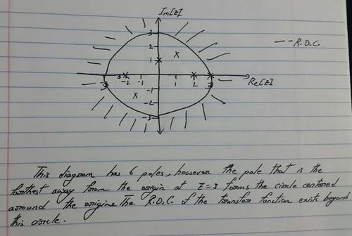
The region of convergence for a right sided signal is always the region outside the pole farthest from the origin. This means that the signal can have many other poles but the one that is farthest away from the origin forms a circle around the origin, beyond which the z-transform is convergent. An example is shown below.
In the diagram above the region of convergence has a total of 6 poles inside it. However since we are assuming this plot to be of a right sided signal, the region of convergence is formed by the region beyond a circle with radius 3 and centered at the origin.
- Left sided signals
If we consider a signal x[n], then the signal is left sided if x[n] is greater than zero for negative values of n as defined by the unit step function. So for example x[n] could be x[n]=(2^n)*u[-n-1] which is a left sided signal which starts at n=-1 and goes on to negative infinity. The region of convergence for a left sided signal is always the region inside the pole closest to the origin. This means that the signal can have many other poles on the z-plane but the one that is closest to the origin forms a circle around the origin, inside which the z-transform is convergent. An example is shown below.
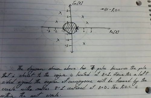
The diagram above shows a pole-zero plot for a left sided signal. The plot has 7 poles in total. The pole located closest to the origin is at z=1. Since this is a left sided signal, the region of convergence is within the circle with radius 1, centered at the origin and going through the pole at z=1.
- Two sided signals
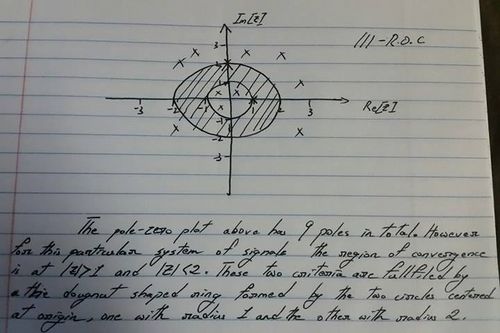
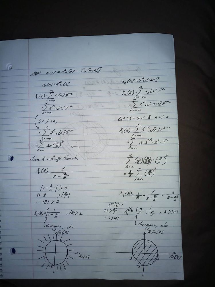
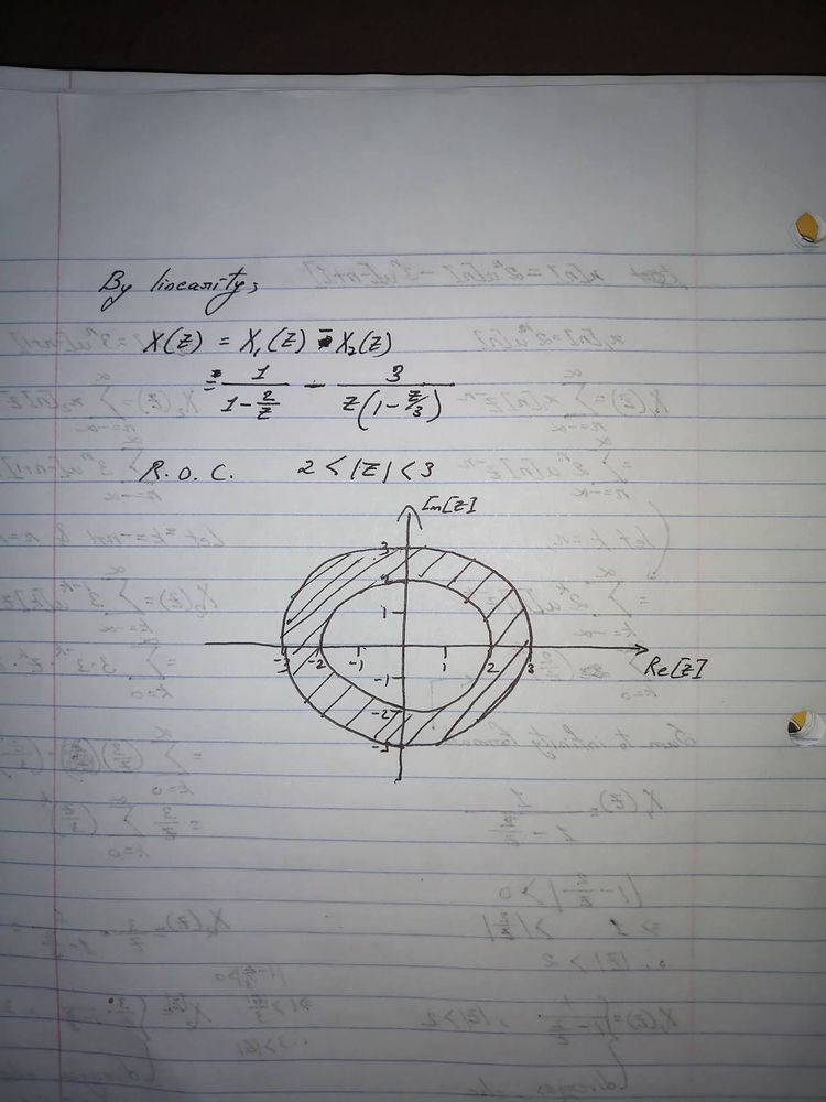
If we consider a signal x[n], then the signal is two sided if x[n] is greater than zero for both positive and negative values of n as defined by the unit step function. So for example x[n] could be x[n]=(2^n)*u[-n-1] + (2^n)*u[n-1] which is a two sided signal which starts once at n=1 and again at n=-1 and goes on to positive and negative infinity. The region of convergence for two sided signals usually forms the shape of a doughnut. There can be many poles for the signal but the region of convergence is alway bounded by a doughnut shaped ring which goes through two poles and the ring does not contain any poles inside. This doughnut shaped ring can be formed by any two poles however with different poles we will get different criterias for the region of convergence for the signal. This is shown below.
The pole-zero plot above has 9 poles in total. However for this particular system of signals, the region of convergence is at |z|>1 and |z|<2. These two criteria are fulfilled by the doughnut shaped ring formed by the two circles centered at origin, one with radius 1 and the other with radius 2.
4. Mathematical Examples
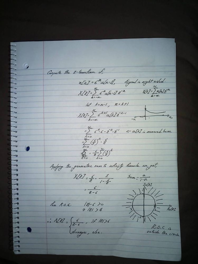
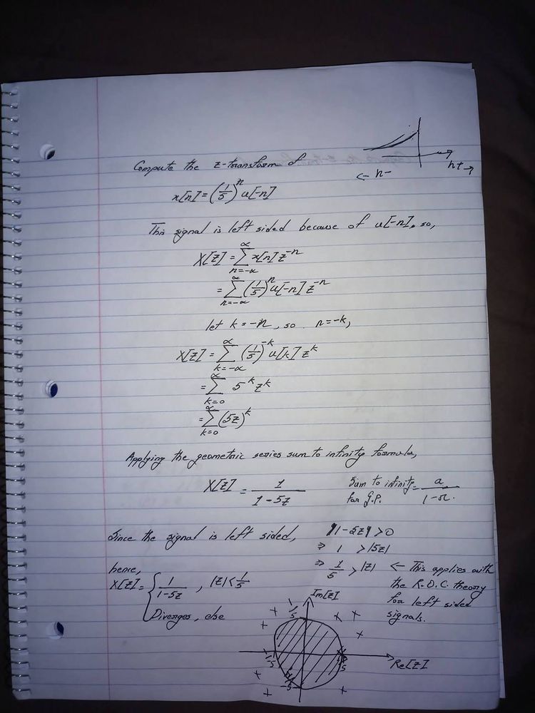
In this section we are going to see how to compute the z-transform of right-sided, left-sided and two-sided signals. Each of the transforms will be accompanied by an image of the solution and a video of how the computation is performed.
* Z-transform
Z-transform of Right Sided signal explanation
Z-transform of Left Sided Signal explanation
Z-trasform of two sided signal explanation
* Inverse Z-transform
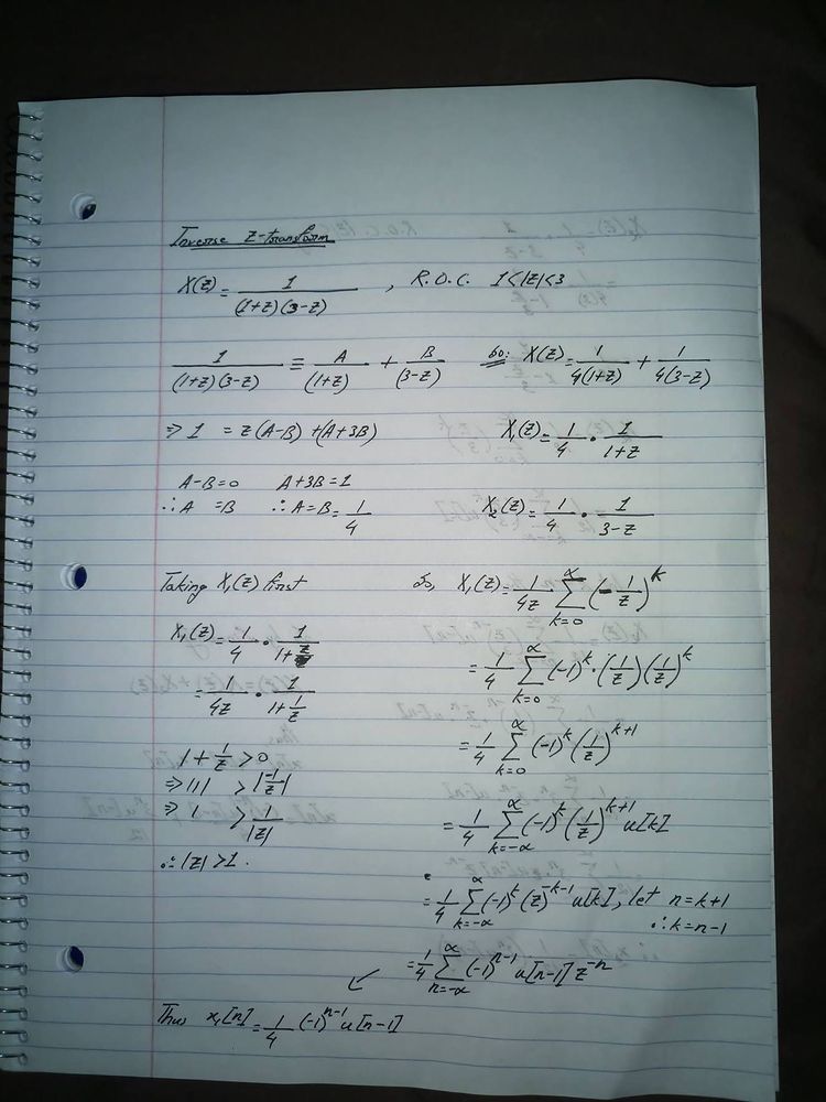
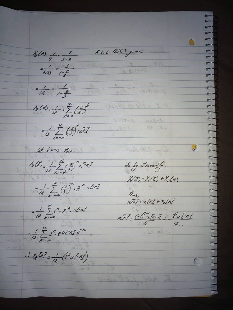
For the inverse z-transform we will look at this calculation for a two sided signal as this will include examples of both a right sided signal and a left sided signal
Inverse z-transform calculation explanation
5. References
The concepts and methods used in this project were mainly taken from the knowledge available in the following websites.
1. Introduction to the z-transform
2. Z-tansform, Wikipedia
3. Z-transform's relation to DTFT, MIT Lecture
4. Region of Convergence Examples
5. Z-transform properties, Tutorialspoint
6. Introduction to the z-transform, YouTube Lecture Video
7. Examples taken from ECE-438 Fall, 2016
8. Examples taken from ECE-438, Fall-2015

