| (4 intermediate revisions by the same user not shown) | |||
| Line 1: | Line 1: | ||
| − | '''Mutual Inductance Sign Calculation + Dot Convention''' | + | '''Mutual Inductance Sign Calculation + Dot Convention''' |
---- | ---- | ||
| Line 5: | Line 5: | ||
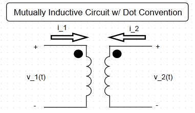
In DeCarlo and Lin's linear circuits textbook [1], a mutually inductive circuit of the following form (Fig. 1) is presented along with a general set of equations (Fig. 2). The signs of the general equation are determined by the 'Rule for the Induced Voltage Drop Due to Mutual Inductance'. Presented here is an algorithmic method to calculate the 4 signs of the set of voltage equations, as well rule that bounds the set of possible sign configurations. | In DeCarlo and Lin's linear circuits textbook [1], a mutually inductive circuit of the following form (Fig. 1) is presented along with a general set of equations (Fig. 2). The signs of the general equation are determined by the 'Rule for the Induced Voltage Drop Due to Mutual Inductance'. Presented here is an algorithmic method to calculate the 4 signs of the set of voltage equations, as well rule that bounds the set of possible sign configurations. | ||
| − | [ | + | [[Image:Mutually_inductive_ckt.JPG| ]] |
Fig. 1 | Fig. 1 | ||
| Line 19: | Line 19: | ||
Assuming that the values of <math>L_1</math>, <math>L_2</math>, and <math>M</math> are fixed, only the sign configuration needs to be determined. This problem can be conceptually simplified by only considering the 'sign matrix', which denotes the coefficient signs of the general equations as follows: | Assuming that the values of <math>L_1</math>, <math>L_2</math>, and <math>M</math> are fixed, only the sign configuration needs to be determined. This problem can be conceptually simplified by only considering the 'sign matrix', which denotes the coefficient signs of the general equations as follows: | ||
| − | [ | + | [[Image:Sign_matrix.png|Sign_matrix.png]] |
| − | + | Fig. 3 | |
We note that three binary variables (can only be positively-oriented or negatively-oriented) determine the signs: | We note that three binary variables (can only be positively-oriented or negatively-oriented) determine the signs: | ||
| Line 29: | Line 29: | ||
The sign associated with current directions is defined by the passive convention (positive if current flows from positive voltage terminal to negative voltage terminal). The sign associated with dot orientation is positive if dots are positioned at same voltage terminal (ie dots both at positive or both at negative voltage terminals), and negative if dots are positioned at opposite terminals. | The sign associated with current directions is defined by the passive convention (positive if current flows from positive voltage terminal to negative voltage terminal). The sign associated with dot orientation is positive if dots are positioned at same voltage terminal (ie dots both at positive or both at negative voltage terminals), and negative if dots are positioned at opposite terminals. | ||
| − | Given the form of the general equations, the sign matrix can be determined by consulting the following sign dependencies | + | Given the form of the general equations, we can observe which terms contribute to which elements of the sign matrix. Thus, the sign matrix can be determined by consulting the following 'sign dependencies', where 'dir' indicates sign due to current 'direction' and 'dot' indicates sign due to orientation of 'dots'. |
[[Image:Sign_dependencies.JPG| ]] <math>for</math> [[Image:Xnor.JPG| ]] | [[Image:Sign_dependencies.JPG| ]] <math>for</math> [[Image:Xnor.JPG| ]] | ||
| Line 38: | Line 38: | ||
'''Bounding of Possible Sign Configurations''' | '''Bounding of Possible Sign Configurations''' | ||
| − | Because I failed to encounter a sign configuration with an odd distribution of signs (eg a=- b=+ c=+ d=+) in working through practice problems, I was curious if such a configuration was possible. Observing that there are only 3 binary variables, a binary table can be constructed by consulting the sign | + | Because I failed to encounter a sign configuration with an odd distribution of signs (eg a=- b=+ c=+ d=+) in working through practice problems, I was curious if such a configuration was possible. Observing that there are only 3 binary variables, a binary table can be constructed by consulting the sign dependency table (see Fig. 4). |
[[Image:Sign_table.JPG| 360x360]] | [[Image:Sign_table.JPG| 360x360]] | ||
Fig. 5 | Fig. 5 | ||
| − | This table enumerates all the possible cases, and explicitly proves that there cannot be an odd sign configuration. Thus, this rule can be used to verify that the calculated sign matrix of a mutual inductance is not incorrect (however, it does not prove that the calculated sign matrix ''is'' correct). | + | This table enumerates all the possible cases, and explicitly proves that there cannot be an odd sign configuration. Thus, this rule can be used to verify that the calculated sign matrix of a mutual inductance circuit is not incorrect (however, it does not prove that the calculated sign matrix ''is'' correct). |
---- | ---- | ||
Latest revision as of 14:17, 1 May 2016
Mutual Inductance Sign Calculation + Dot Convention
In DeCarlo and Lin's linear circuits textbook [1], a mutually inductive circuit of the following form (Fig. 1) is presented along with a general set of equations (Fig. 2). The signs of the general equation are determined by the 'Rule for the Induced Voltage Drop Due to Mutual Inductance'. Presented here is an algorithmic method to calculate the 4 signs of the set of voltage equations, as well rule that bounds the set of possible sign configurations.
Fig. 1
$ v_1(t) = \pm \ L_1\frac{di_1}{dt} \pm \ M\frac{di_2}{dt} \ \ \ \ \ (17.4a \ \ [1]) $
$ v_2(t) = \pm \ L_2\frac{di_2}{dt} \pm \ M\frac{di_1}{dt} \ \ \ \ \ (17.4b \ \ [1]) $
Fig. 2
Algorithmic Determination of Signs
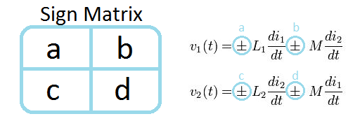
Assuming that the values of $ L_1 $, $ L_2 $, and $ M $ are fixed, only the sign configuration needs to be determined. This problem can be conceptually simplified by only considering the 'sign matrix', which denotes the coefficient signs of the general equations as follows:
Fig. 3
We note that three binary variables (can only be positively-oriented or negatively-oriented) determine the signs:
- direction of $ i_1 $
- direction of $ i_2 $
- orientation of dots
The sign associated with current directions is defined by the passive convention (positive if current flows from positive voltage terminal to negative voltage terminal). The sign associated with dot orientation is positive if dots are positioned at same voltage terminal (ie dots both at positive or both at negative voltage terminals), and negative if dots are positioned at opposite terminals.
Given the form of the general equations, we can observe which terms contribute to which elements of the sign matrix. Thus, the sign matrix can be determined by consulting the following 'sign dependencies', where 'dir' indicates sign due to current 'direction' and 'dot' indicates sign due to orientation of 'dots'.
Fig. 4
Bounding of Possible Sign Configurations
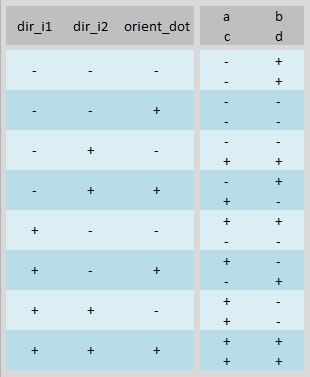
Because I failed to encounter a sign configuration with an odd distribution of signs (eg a=- b=+ c=+ d=+) in working through practice problems, I was curious if such a configuration was possible. Observing that there are only 3 binary variables, a binary table can be constructed by consulting the sign dependency table (see Fig. 4).
Fig. 5
This table enumerates all the possible cases, and explicitly proves that there cannot be an odd sign configuration. Thus, this rule can be used to verify that the calculated sign matrix of a mutual inductance circuit is not incorrect (however, it does not prove that the calculated sign matrix is correct).
References
[1] R. DeCarlo and P.M. Lin, "Magnetically Coupled Circuits and Transformers," in Linear Circuit Analysis: Time Domain, Phasor and Laplace Transform Approach. Dubuque, IA: KendallHunt, 2001, pp. 884-890.


