| (5 intermediate revisions by 2 users not shown) | |||
| Line 17: | Line 17: | ||
<br> [[Image:Block.jpg]] <br> | <br> [[Image:Block.jpg]] <br> | ||
| − | '''Theory'''<br> Upsampling in the frequency domain. It can be obtain in two different ways.<br> <br> [[Image:Theroy.jpg]] '''or ''' [[Image:CodeCogsEqn.jpg]] | + | '''Theory'''<br> Upsampling in the frequency domain. It can be obtain in two different ways.<br> <br> [[Image:Theroy.jpg]] '''or ''' [[Image:CodeCogsEqn.jpg]]<br> |
| − | + | ||
| − | <br> | + | |
| − | + | ||
| − | + | ||
| − | + | ||
| − | + | ||
| − | + | ||
| − | + | ||
| − | + | ||
| − | + | ||
| − | + | ||
| − | + | ||
| − | + | ||
<br> | <br> | ||
| Line 40: | Line 27: | ||
<br> | <br> | ||
| − | Here is the example of | + | Here is the example of sampling signal.<br> |
[[Image:Graphex.jpg]] | [[Image:Graphex.jpg]] | ||
| Line 52: | Line 39: | ||
[[Image:Graphex3.jpg]] | [[Image:Graphex3.jpg]] | ||
| − | Here is the final | + | Here is the final upsampling signal.<br> |
[[Image:Graphex5.jpg]] | [[Image:Graphex5.jpg]] | ||
| − | '''Conclusion''' | + | '''Conclusion''' |
| − | + | ||
| + | Upsampling by D inserts D - 1 zeros between every element of the original signal. Upsampling can create imaging artifacts. Lowpass filtering following upsampling can remove these imaging artifacts. In the time domain, lowpass filtering interpolates the zeros inserted by upsampling. | ||
| + | |||
| + | <br> | ||
| + | |||
| + | ==[[Upsampling_Hyungsuk_Kim_slecture_review|Questions and comments]]== | ||
| + | |||
| + | If you have any questions, comments, etc. please post them on [[Upsampling_Hyungsuk_Kim_slecture_review|this page]]. | ||
| + | ---- | ||
| + | [[2014_Fall_ECE_438_Boutin_digital_signal_processing_slectures|Back to ECE438 slectures, Fall 2014]] | ||
Latest revision as of 09:01, 14 March 2015
OUTLINE
1. Introduction
2. Theory
3. Example
4. Conclusion
_________________________________________________________________________________________________________
Introduction
Upsampling is the process of increasing sampling rate of discret-time signal. In this slecture, I will discuss about how it works and example of upsampling.
Theory
Upsampling in the frequency domain. It can be obtain in two different ways.
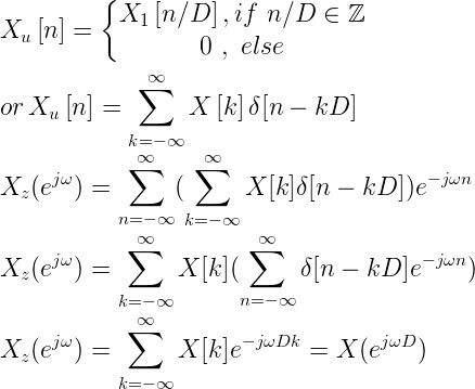 or
or 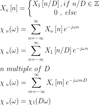
Example
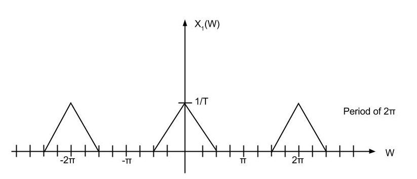
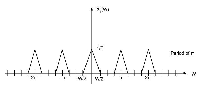
Upsampling rate D = 2
Here is the example of sampling signal.
Upsampling rate D = 2 is applied.
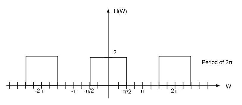
Low-Pass filter of cutoff π/2, gain 2 is applied.
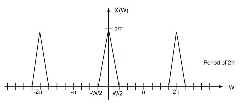
Here is the final upsampling signal.
Conclusion
Upsampling by D inserts D - 1 zeros between every element of the original signal. Upsampling can create imaging artifacts. Lowpass filtering following upsampling can remove these imaging artifacts. In the time domain, lowpass filtering interpolates the zeros inserted by upsampling.
Questions and comments
If you have any questions, comments, etc. please post them on this page.


