| Line 588: | Line 588: | ||
Did more research on serial connections to figure out why the Pandaboard was not communicating with the micro. I found an article I came across previously stating "When PCs are connected back-to-back each end is acting as a DTE (there is no DCE in this case) and consequently certain signals may have to be looped in the connection to satisfy any input signal requirement." This is, right now, the only possible reason I can think of as to why the two are not communicating.<br> | Did more research on serial connections to figure out why the Pandaboard was not communicating with the micro. I found an article I came across previously stating "When PCs are connected back-to-back each end is acting as a DTE (there is no DCE in this case) and consequently certain signals may have to be looped in the connection to satisfy any input signal requirement." This is, right now, the only possible reason I can think of as to why the two are not communicating.<br> | ||
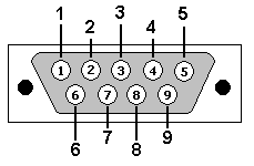
http://www.zytrax.com/images/rs232_db9.gif <br> | http://www.zytrax.com/images/rs232_db9.gif <br> | ||
| + | |||
| + | Pin Signal In/Out Description | ||
| + | 1 DCD In Data Carrier Detect | ||
| + | 2 RxD In Receive Data | ||
| + | 3 TxD Out Transmit Data | ||
| + | 4 DTR Out Data Terminal Ready | ||
| + | 5 GND - Ground | ||
| + | 6 DSR In Data Set Ready | ||
| + | 7 RTS Out Request To Send | ||
| + | 8 CTS In Clear To Send | ||
| + | 9 RI In Ring Indicator | ||
| + | |||
This is the male DB9 pin out. We will just need to add a jumper between pins 7 and 8 and get rid of the wires. Pin 7 is RTS and pin 8 is CTS. | This is the male DB9 pin out. We will just need to add a jumper between pins 7 and 8 and get rid of the wires. Pin 7 is RTS and pin 8 is CTS. | ||
</td> | </td> | ||
Revision as of 11:38, 29 November 2011
Contents
[hide]Jason Holmes - Design Notebook
Week of Sept. 19 |
|
September 21, 2011 (1.5 hours):
|
|
September 22, 2011 (20 minutes):
|
|
September 23, 2011 (1 hour):
|
| WEEK SUMMARY: Accomplishments: Obtained usernames for HKUST members
|
Week of Sept. 26 |
|
September 27, 2011 (45 minutes):
|
|
September 27, 2011 (30 minutes):
|
|
September 28, 2011 (1 hour):
|
|
September 29, 2011 (45 minutes):
|
|
September 30, 2011 (1.5 hour):
|
| WEEK SUMMARY: Accomplishments: Completed preliminary block diagram layout of system. Decided on potential processor family.
|
Week of Oct. 3 |
|
October 6, 2011 (2 hours):
|
|
October 7, 2011 (1 hour):
|
|
October 7, 2011 (1.5 hours):
|
| WEEK SUMMARY: Accomplishments: Finished poster for VIP poster session
|
Week of Oct. 10 |
|
October 11, 2011 (30 minutes):
|
|
October 13, 2011 (1 hour):
|
|
October 14, 2011 (1.5 hours):
|
| WEEK SUMMARY: Accomplishments: Decided on a development board to begin prototyping.
|
Week of Oct. 17 |
|
October 17, 2011 (30 minutes):
|
|
October 17, 2011 (1 hour):
|
|
October 18, 2011 (3 hours):
IP Camera:TRENDnet TV-IP110WN Wireless N Internet Camera
|
|
October 19, 2011 (2 hours):
|
|
October 20, 2011 (1 hour):
|
| WEEK SUMMARY: Accomplishments:
|
Week of Oct. 24 |
|
October 25, 2011 (3.2 hours):
(640 x 480 pixels) X (2 bytes per pixel) = 614,400 bytes per frame All of the CMOS cameras output in a RGB format or similar - raw image data. For most cameras, this is 16 bits per pixel. Without doing our own compression, this image data would be impossible to send wirelessly. There is a library for C to convert RGB data to JPEG format, which then possibly be converted to MJPEG on the controller side. This could possibly be used on-board, but the speed would have to be tested.
|
|
October 28, 2011 (1.5 hours):
|
| WEEK SUMMARY: Accomplishments:
|
Week of Oct. 31 |
|
November 1, 2011 (4.5 hours):
|
|
November 3, 2011 (7 hours):
|
|
November 3, 2011 (1.5 hours):
|
| WEEK SUMMARY: Accomplishments: Received tanks
|
Week of Nov. 7 |
|
November 8, 2011 (3 hours):
|
|
November 9, 2011 (3 hours):
|
|
November 10, 2011 (2 hours):
|
|
November 11, 2011 (2 hours):
|
| WEEK SUMMARY: Accomplishments: Completed design review
|
Week of Nov. 14 |
| WEEK SUMMARY: Accomplishments: Got a webcam feed - though not a great feed
|
Week of Nov. 21 |
|
November 23, 2011 (3 hours):
|
|
November 24, 2011 (6 hours):
|
|
November 25, 2011 (1.5 hours):
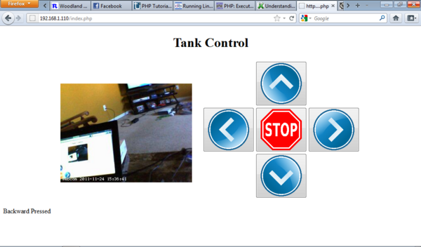
$serial = new phpSerial; $serial->deviceSet("/dev/tty0"); $serial->confBaudRate(2400); $serial->deviceOpen(); switch ($_POST['D']) { case "Forward": echo "Forward Pressed";
$serial->sendMessage("F");
break;
case "Left": echo "Left Pressed";
$serial->sendMessage("L");
break;
case "Right": echo "Right Pressed";
$serial->sendMessage("R");
break;
case "Backward": echo "Backward Pressed";
$serial->sendMessage("B");
break;
case "Stop": echo "Stop Pressed";
$serial->sendMessage("S");
break;
default: echo "Initial page load"; } ?> |
|
November 25, 2011 (30 minutes):
|
| WEEK SUMMARY: Accomplishments:
|
Week of Nov. 28 |
|
November 28, 2011 (8 hours):
|
|
November 29, 2011 (30 minutes):
Pin Signal In/Out Description 1 DCD In Data Carrier Detect 2 RxD In Receive Data 3 TxD Out Transmit Data 4 DTR Out Data Terminal Ready 5 GND - Ground 6 DSR In Data Set Ready 7 RTS Out Request To Send 8 CTS In Clear To Send 9 RI In Ring Indicator This is the male DB9 pin out. We will just need to add a jumper between pins 7 and 8 and get rid of the wires. Pin 7 is RTS and pin 8 is CTS. |
|
November , 2011 ( hours):
|
|
November , 2011 ( minutes):
|
| WEEK SUMMARY: Accomplishments:
|

