Computed Tomography (CT)
A slecture by ECE student Sahil Sanghani
Partly based on the ECE 637 material of Professor Bouman.
Contents
[hide]Introduction
Computed Tomography (CT) is a X-ray based method of 3D imaging. Other 3D imaging techniques are Magnetic Resonance Imaging (MRI) and Positron Emission Tomography (PET). Both CT and PET use tomographic reconstruction to create their 3D representations. Tomography has a variety of uses in the medical field, remote nondestructive sensing, RADAR, and SAR.
CT Scanner Structure
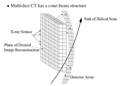
Figure 1 shows a typical CT scanner used for medical imaging. The CT scanner is composed to two main parts: the bed and the scanner. The bed horizontally translates through the scanner, which houses the rotating X-ray source and detector. Figure 2 shows a CT scanner without the cover. The X-ray source, detector and travel have been highlighted. As the bed translates horizontally through the scanner, the scanner collects multiple data scans and processes them. Because the scanner is collecting as the patient moves through it, the path of the scan is actually helical, as shown in Figure 3.
Photon Attenuation
There are a couple assumptions and approximations that are used in the CT scanning and recording technology. The first approximation is that the X-ray source emits photons that supposedly travel in a straight line. This can be achieved with a pinhole collimator as shown in Figure 4. Just like how a lens focuses light, the pinhole collimator focuses X-rays. Typically a pinhole isn't used because the diffraction effects cause constructive and destructive interference. However, since the wavelength of X-rays is so small, the diffraction artifacts don't affect the pinhole collimator. Thus we can assume that the X-rays that come through the pinhole propagate in a straight line.
The second assumption is that the energy loss from absorbed photons is significant. Each photon that travels through the material has a probability of being "absorbed" for each increment of distance it travels. Being "absorbed" means that the photon is scattered, changing its direction and wavelength enough for the detector to miss that photon. The scattered photons dissipate into the surrounds in the form of heat.
The third assumption is that new photons are created only at the source. Photons can only be absorbed (scattered) after they leave the source.
These three assumptions imply that photons emitted from the X-ray source either get to the detector directly opposite the pinhole or don't get there.
Extracting the Line Integral for Convolution Back Projection
$ x: $= the depth into the material measured in cm
$ Y_x: $= the number of photons at depth $ x $.
$ \lambda_x = E[Y_x]: $= the expectation of the number of photons at depth $ x $
$ \mu(x): $= density of the material being scanned as a function of $ x $ with the units of $ cm^{-1} $.
$ dx: $= distance increment and voxel depth
$ P\{Y_x = k\}: $= the probability that there are $ k $ photons at depth $ x $ cm
The number of protons present at a depth $ x $ is modeled by a Poisson Random Variable. This fact implies:
$ P\{Y_x = k\} = \frac{e^{-\lambda_x}\lambda_x^k}{k!} $
Now using Beer's law, it can be said that the adsorption rate of photons is proportional to the density of the material and the number of photons entering the material.
$ -\Delta\lambda_x = \lambda_x\mu(x)\Delta x \ $
Which can be rearranged to:
$ \frac{d\lambda_x}{dx} = -\mu(x)\lambda_x $
The above equation means that the change in the number of photons in a given voxel is proportional to the number of photons entering the material at depth $ x $ and to the material density. Since the number of photons exiting the voxel can only decrease (see third assumption above), the rate of change will always be negative. Since the rest of the values are positive, the minus sign must be included to compensate.
From integration it can be seen that
$ \lambda_x = \lambda(0) e^{-\int_0^x \mu(\tau)d\tau} $
This type of solution will be unique if there is a boundary condition, $ \lambda(0) $. This equation implies that the number of photons that exit the voxel will be less than or equal to the number that enters it. Because $ \mu(\tau) $ is always greater than zero, the power of the exponential will always be negative. This equation can be rearranged to extract an attenuation factor as follows
$ \frac{\lambda(x)}{\lambda(0)} = e^{-\int_0^x \mu(t)dt} $
Now taking the natural log of both sides:
$ \begin{align} \int_0^x \mu(t)dt &= -ln(\frac{\lambda_x}{\lambda(0)})\\ &\approx -ln(\frac{Y_x}{\lambda(0)}) \end{align} $
Note: $ \lambda(0) $ is determined from an empty calibration of the CT scanner. This is typically done by the technician the morning of the CT scans.
The CT scanner measures $ -ln(\frac{\lambda_x}{\lambda(0)}) $. This measurement is repeatedly collected all along the object at various angles to produce many projections with their own line integrals. These line integrals are used in tomographic reconstruction. Once all the line integrals have been computed, convolution back projection can be used to produce slices for each line integral which will stack to become a 3D representation of the patient's body.
References:
[1] C. A. Bouman. ECE 637. Class Lecture. Digital Image Processing I. Faculty of Electrical Engineering, Purdue University. Spring 2013.
[2] Original photo rights owner could not be found. If the owner of this picture wants it to be taken down, please contact rheateam@gmail.com.
Questions and Comments
Please post your questions and comments on the discussion page.


