Jason Holmes - Design Notebook

Week of Sept. 19

September 21, 2011 (1.5 hours):
Participated in teleconference with HKUST. The discussion included possible processor options as well as the general scope of the project. After meeting with Prof. Boutin, she said they would be happy to add usernames for the HKUST team members. Today, I received the new usernames for the HKUST students created for the Rhea page - emailed them to the team members.

September 22, 2011 (20 minutes):
Updated the Rhea page with information about the teleconference for those who were not there.

September 23, 2011 (1 hour):
Attended weekly meeting with VIP group.


WEEK SUMMARY:

Accomplishments: Obtained usernames for HKUST members
Weekly Work Total: 2.7 hours
Project Work Total: 2.7 hours


Week of Sept. 26

September 27, 2011 (45 minutes):
Researched processors and wireless modules, updated brainstorming session on the Rhea page. Still a little unsure of what I think.

September 27, 2011 (30 minutes):
Created a whenisgood address to organize a group meeting to create a diagram of the desired system before our group meeting on Friday. Set meeting time after results from team members came in.

September 28, 2011 (1 hour):
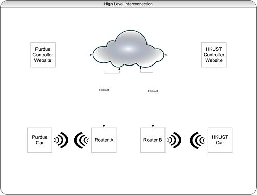
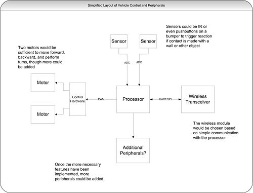
Met with group members to create system diagram and discuss processor choice.

September 29, 2011 (45 minutes):
Finalized system diagram and did more research on a processor/development board.

High Level.jpg
Low Level.jpg

September 30, 2011 (1.5 hour):
Attended weekly VIP group meeting. Updated block diagrams to reflect discussions at the meeting and updated the Rhea page with notes from the meeting.


WEEK SUMMARY:

Accomplishments: Completed preliminary block diagram layout of system. Decided on potential processor family.
Weekly Work Total: 4.5
Project Work Total: 7.2


Week of Oct. 3

October 6, 2011 (2 hours):
Attended group meeting to design initial draft of poster for VIP poster session. Finished initial draft of poster at home and posted a pdf version to the Rhea site to be reviewed at Friday's meeting. Link here : Poster

October 7, 2011 (1 hour):
Revised poster based on Dr. Johnson's initial impressions and researched wireless transceivers.

October 7, 2011 (1.5 hours):
Attended weekly group meeting and updated Rhea page with meeting minutes.


WEEK SUMMARY:

Accomplishments: Finished poster for VIP poster session
Weekly Work Total: 4.5 hours
Project Work Total: 11.7 hours


Week of Oct. 10

October 11, 2011 (30 minutes):
Reformatted and submitted poster to be printed.

October 13, 2011 (1 hour):
Did research on development boards presented on Friday's meeting.

October 14, 2011 (1.5 hours):
Attended weekly meeting. Picked up development board!


WEEK SUMMARY:

Accomplishments: Decided on a development board to begin prototyping.
Weekly Work Total: 3 hours
Project Work Total: 14.7 hours


Week of Oct. 17

October 17, 2011 (30 minutes):
Updated Rhea page with Oct. 14 meeting minutes

October 17, 2011 (1 hour):
Got "Blinky" to run using KEIL software!

Blinky

October 18, 2011 (3 hours):
Attended scheduled meeting to decide on project parameters.
Vehicle Platform: Airsoft RC Electric Panzer Giant BattleTank

  • This vehicle was chosen because of its size and peripherals. It has plenty of room with a size of 2.5ft x 1ft.
  • It also has a moving turret already which is perfect for mounting a camera. In addition, the tank fires air soft pellets! This control can be investigated and added to the specs for the control of our vehicle if we want it to be able to fire.
  • We were concerned with the speed of the R/C cars of equivalent size - a lot of them up to 60mph. In addition, their cost was ~$150 and we are anticipating having to buy 2 to compensate for tearing one apart. At such a high speed, sensors to increase the autonomy of the vehicle would be virtually useless.


Wireless Module: RN-XV module

  • This module was simply chosen because of price and because it communicates through UART which is available for the Cortex-M3

IP Camera:TRENDnet TV-IP110WN Wireless N Internet Camera

  • It was very hard to find an appropriate IP camera. We wanted to find a camera that didn't depend on software. This camera is on the lower end of prices (hundreds were looked at) and it should work great.
  • All IP cameras have to be assigned a static IP address. This will need to be an option on the controlling website. Even if the camera was integrated, an IP update on the vehicle would still have to occur.


IR sensors and pushbuttons were chosen based on price. There is no need for long rang IR sensors.

October 19, 2011 (2 hours):
I did more research on IP cameras as I felt very unsure of using one. Not only did I feel like using one would be lame, there were just too many problems to deal with. One major problem is that IP cameras require that you connect to them via Ethernet and set up a static IP address for them. This would be extremely inconvenient for our purposes as every change in location would require a manual change in the camera's IP address. Also, most IP cameras require that you use the manufacturers software to access them - usually with a login and password on a browser. With time I'm sure our group could hack this requirement, but that is not really something we would like to do. (Not to mention IP cameras run ~$90 for the cheaper models)

I found a $10 CMOS camera on SparkFun, and one of the comments stated that someone had success interfacing to it with a Cortex M3! This will cause a change in our wireless transceiver as the one we chose previously would not be able to handle the throughput needed. We will be able to use the same line of transceivers, we will just have to pay more. There are many other CMOS cameras that we can choose from and this will give us greater flexibility in terms of implementation. It will be much harder to deal with the video feed ourselves, but will surely be more rewarding in the end.

Also attended VIP poster session which went really well.

October 20, 2011 (1 hour):
Found a new wireless transceiver that can potentially handle the data rate for the video feed and has i2c and well as other interfaces. More details on this later as I dig into the datasheet. Also created groups that we will break up into for project development and updated all of my research on this page: Research


WEEK SUMMARY:

Accomplishments:
Weekly Work Total: 8.5 hours
Project Work Total: 23.2 hours


Week of Oct. 24

October 25, 2011 (3.2 hours):
Met with group to complete tasks discussed at Friday's meeting. Last week we decided against using an IP camera because of the limitations. This week we looked into the requirements of implementing our own camera module. Unfortunately, the math did not come out in our favor. IP cameras use MJPEG compression internally before outputting the video to the web - which natively streams the MJPEG format. If we did not implement our own compression:

(640 x 480 pixels) X (2 bytes per pixel) = 614,400 bytes per frame
(614,400 bytes per frame) X (20 frames per second) = 12.3 MB/s output = 98.3 Mbps output

All of the CMOS cameras output in a RGB format or similar - raw image data. For most cameras, this is 16 bits per pixel. Without doing our own compression, this image data would be impossible to send wirelessly. There is a library for C to convert RGB data to JPEG format, which then possibly be converted to MJPEG on the controller side. This could possibly be used on-board, but the speed would have to be tested.


October 28, 2011 (1.5 hours):
Attended weekly VIP meeting. Updated Rhea page with meeting minutes and created a Doodle poll for Video Conference #2 with HKUST.


WEEK SUMMARY:

Accomplishments:
Weekly Work Total: 4.7 hours
Project Work Total: 27.9 hours


Week of Oct. 31

November 1, 2011 (4.5 hours):
Group disassembled one tank and found out exactly how the controls work. The controller (left/right and up/down) are simply switches. There are 4 relays on the basic circuit board - two for each drive motor. One switches on to drive each motor forward, and one for backward, supplying the battery's voltage and current. The turret is controlled by a small motor connected to a large gear. We will definitely change this as it is hard to control.

I located enough information to drive a very slow PWM channel that switched one pin on and off. We then constructed a circuit to drive the motor. To be on the safe side, we decided to optically isolate the drive to the motor. We calculated the correct resistor values for the BJT we were using and did not get it to work. So we tried it without and still couldn't get it to drive the motor even though all calculations and measurements from the DMM pointed to it working. We called it a night. Pictures and calculations will follow once we retry on Thursday.

November 3, 2011 (7 hours):
Looked at an example PWM program for the micro and looked up information in the datasheet. PWM mode can be chosen for each channel in each of the four timers. This is selected by setting the TIMx_CCMRx register correctly.In PWM mode (1 or 2), TIMx_CNT and TIMx_CCRx are always compared to determine whether TIMx_CCRx≤ TIMx_CNT or TIMx_CNT≤ TIMx_CCRx (depending on the direction of the counter). The duty cycle can be adjusted with the TIMx_CCRx registers. I tried to combine the PWM initialization code with ADC initialization code and LCD code to control the CCR register with the ADC value, but have not gotten it to work yet. Thus the code used manually controlled the the PWM at a specific frequency and duty cycle.

I tried our circuit again for PWM motor speed control, and after an hour or two when the rest of the group came we figured out that the 2N3704 NPN BJT we were using was being fried by the collector to emitter voltage/current. We found this out when we noticed one became burning hot and did not operate correctly. Scott and I went to radio shack and got two TIP 120s (Darlington BJT). We rebuilt the circuit but the motor was still not responding to the PWM input. After probing the circuit we found the the 5V output from the microcontroller was not functioning correctly. We used the Agilent E3631A DC PSU to supply 5V to the rail and the motor finally responded to the PWM output.

Circuit Diagram

November 3, 2011 (1.5 hours):
Attended weekly VIP meeting and updated Rhea page


WEEK SUMMARY:

Accomplishments: Received tanks
Weekly Work Total: 13 hours
Project Work Total: 40.9 hours


Week of Nov. 7

November 8, 2011 (3 hours):
Worked on design review with group.

November 9, 2011 (3 hours):
Continued working on the design review. Acquired the Pandaboard and hooked it up - hit a roadblock as seen in the picture below. I will either need to figure out the password or load a different linux distro onto an SD card so I can actually proceed.

Ubuntu Login Screen

November 10, 2011 (2 hours):
Attended video conference with group from Hong Kong. We decided to meet next week with the agreement that we would each come up with our own version of an appropriate protocol for vehicle control and then compare them and decide on one for both groups next meeting.

Also finalized the design review slides and submitted them.

November 11, 2011 (2 hours):
Practiced and attended design review.


WEEK SUMMARY:

Accomplishments: Completed design review
Weekly Work Total: 10 hours
Project Work Total: 50.9 hours


Week of Nov. 14

November 15, 2011 (3 hours):
Met with group to work on our protocol and other projects. Scott, Kin Chin, and Chris worked to develop a protocol that incorporated some of the ideas that the HK group had proposed on the discussions page.

Meanwhile, I worked on flashing Ubuntu onto an SD card and adding the necessary files to allow it to boot on the Pandaboard. It worked on the first shot! Well, it booted on the first shot. I still had to add about 238MB of other files for the board which, among other things, added the wireless and bluetooth drivers.

I plugged in the webcam obtained from Dr. Swabey and tried running Cheese to see if we could see the video from the camera. It crashed the OS and rebooted. I kept the camera plugged in and tried again but did not get anything. The webcam choice on that app is stuck on /dev/video3 so I will need to do more research to find where the webcam is actually being mounted.

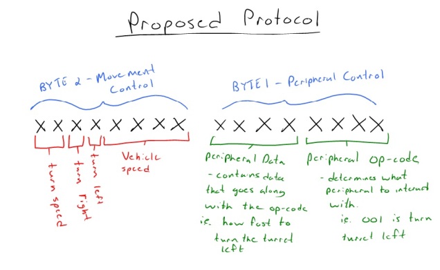
Protocol proposal.jpg
I got back with the rest of the group and we finalized our protocol proposal. Basically, it goes along with the HK teams desire for a 16 bit protocol. The first byte is used for the actual vehicle control. As you can see from the picture, drawn by Scott, there is a bit to signal a right turn, a bit to signal a left turn, and two bits to designate the turn speed. The other four bits will be used for vehicle speed. There are 16 distinct points for vehicle speed that can be utilized, split between forward and reverse. The interpretation of that number (whether signed or unsigned) will be discussed at the video conference.

The second byte will be used for peripheral control. One of the main problems we saw with HK's protocol plan was that the peripheral control didn't make much sense. We decided that the second byte will be split up into two 4 bit values, one designating the peripheral/action and the other being the control value (can be 0 or 1 or a value with higher resolution). We wanted to be able to expand our peripheral control capabilities without having to change the protocol while still keeping the data to 2 bytes.

November 18, 2011 (3 hours):

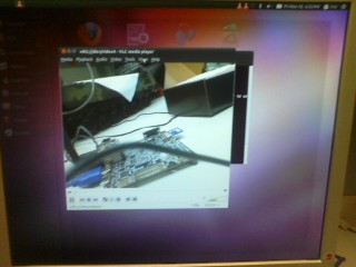
Attended weekly meeting. Due to my lack of success with the webcam feed, I borrowed Dr. Johnson's webcam to try it out. When I tried Cheese, it showed garbage but it at least showed something. I installed VLC and tried out some things. Easiest way I found to find the camera device was to ls in /dev before and after to find out the videoX that it was. I did this with the webcam and found it was /dev/video4, so I ran 'vlc v4l2:///dev/video4' (equivalent to choosing the capture device in the GUI) and the feed worked. The feed did glitch every so often.
Webcam works.jpg


Since this worked, I decided to give up on Cheese and try out VLC for the camera provided by Dr. Swabey. It did show feed, but would glitch and freeze for 30+ seconds often - obviously worthless. After consulting and working with Dr. Swabey who was kind enough to take a look at it, he found that something is not right with the graphics drivers which was causing even just the monitor display to take 20% of the CPU processing power. I tried to play some test *.mpg videos in VLC which didn't even play. Something is obviously wrong. At least I made some progress.


WEEK SUMMARY:

Accomplishments: Got a webcam feed - though not a great feed
Weekly Work Total: 6 hours
Project Work Total: 56.9 hours


Week of Nov. 21

November 23, 2011 (3 hours):
Installed the Apache web server on the pandaboard. I didn't have much success with lighttpd because of my small amount of experience. Apache did not take much configuring. All files for the site need to be in the /var/www directory, where Apache placed a near blank index.html. I tried accessing it via a public IP address which obviously didn't work since I don't have port 80 forwarded on my router. This is currently a concern for trying to connect this to PAL...if PAL does not assign public IP addresses, which I doubt it does, we won't be able to access the site on the board while connected to it. To get this to work, it will take a lot of configuring. However, connecting to it via its local IP in my local network, I was able to view the index.html, so the server was confirmed to be working.

November 24, 2011 (6 hours):
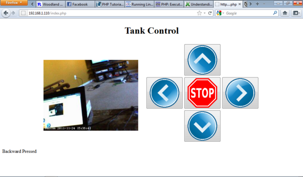
Spent a lot of time today getting the site setup. I added buttons that utilize a php form to send commands. Currently, it just updates which button was pressed on the page, but you can execute commands in linux from php so it should be fairly simple to write to the com port. It took a very long time to get the webcam feed to work. I used a program called webcam, downloaded using 'aptitude install webcam', which I read about online. Once you manually set up a webcam.config file which includes which source (/dev/video0) and video dimensions, among other things. This software takes the webcam feed and writes it to a file in the /var/www directory which can the be accessed just like an image, <img src="webcam.jpg" width=320 height=240>. You start this process by executing 'sudo webcam /etc/webcam.conf &'. Logging onto the site with this image embedded showed only a still image. This is due to the fact that the page only take one image as it loads.

I tried adding the line <meta http-equiv="refresh" content="0"> with caused the page to constantly refresh, and the feed updated continuously. However, this caused the page to be constantly refreshing and that's just not feasible. So, I added in some javascript code that reloads the image at a rate of 20 fps and it looks great.

Tank control site.png


As you can see, I currently have the site echo which button is pressed, which will be the same code that sends commands to the serial port.
Here is my code:

Tank Control Site Code

November 25, 2011 (1.5 hours):
I found a php class online that helps with the php to serial connection, with a class that provides methods for setting the baud rate, opening and closing the port, and sending and receiving data. Here is the php code on the site using these methods. (Note: actual port still untested)

<?php include "php_serial.class.php"

$serial = new phpSerial; $serial->deviceSet("/dev/tty0"); $serial->confBaudRate(2400); $serial->deviceOpen();

switch ($_POST['D']) { case "Forward":

 echo "Forward Pressed";
 $serial->sendMessage("F");
 break;

case "Left":

 echo "Left Pressed";
 $serial->sendMessage("L");
 break;

case "Right":

 echo "Right Pressed";
 $serial->sendMessage("R");
 break;

case "Backward":

 echo "Backward Pressed";
 $serial->sendMessage("B");
 break;

case "Stop":

 echo "Stop Pressed";
 $serial->sendMessage("S");
 break;

default:

 echo "Initial page load";

} ?>

November 25, 2011 (30 minutes):
Created a server on my netbook while on campus...no public IP from PAL, which I figured would be the case. For this semester, any demo for HK will have to be done using a different wireless connection.


WEEK SUMMARY:

Accomplishments: Web server successfully setup with a functioning index
Weekly Work Total: 11 hours
Project Work Total: 67.9 hours


Week of Nov. 28

November 28, 2011 (8 hours):
Spent a good deal of time debugging my index.php and making it work with the php_serial.class.php. I had to make some changes so that the php errors and warning would show up. In the php.ini file, I changed display_errors = Off and error_reporting = E_ALL. Errors/warning still did not show up so, in the httpd.conf for apache2, I added "php_flag display_errors on" and "php_value error_reporting 2039" which resulted in a load of error files echoed on index.php upon a refresh. Essentially, any access by the script was getting an "Access denied". All of the commands use stty. The command by the script, which took "/dev/ttyO2" as an argument, was essentially running the command "stty -F /dev/ttyO2" and getting the access denied reply. I tried this command in a terminal on the board and had no trouble running it.

Obviously the permissions were not right, so I ran "sudo chmod 777 /dev/ttyO2" and reloaded the page - no more errors. I hooked up the scope to the transfer line of the serial port on the pandaboard and pressed the buttons on the site from my netbook and saw blips on the scope - finally things were working right.

Scott hooked up the pandaboard to his laptop and ran putty. It works!

File:Pandaboard serial.avi

Scott, Kin Chin, Michael, Matt, and Chris worked on figuring out the initializations and main code for the microcontroller. Once they had what they thought would work, we hooked the two boards up - nothing. We tried the micro with putty - and it worked! So, we currently have the Pandaboard<-->laptop and micro<-->laptop connections working. However, at this point we cannot get the two to communicate with each other.

November 29, 2011 (30 minutes):
Did more research on serial connections to figure out why the Pandaboard was not communicating with the micro. I found an article I came across previously stating "When PCs are connected back-to-back each end is acting as a DTE (there is no DCE in this case) and consequently certain signals may have to be looped in the connection to satisfy any input signal requirement." This is, right now, the only possible reason I can think of as to why the two are not communicating.
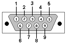
rs232_db9.gif

Pin----Signal--In/Out---Description
1-------DCD-----In------Data Carrier Detect
2-------RxD-----In------Receive Data
3-------TxD-----Out-----Transmit Data
4-------DTR-----Out-----Data Terminal Ready
5-------GND-------------Ground
6-------DSR-----In------Data Set Ready
7-------RTS-----Out-----Request To Send
8-------CTS-----In------Clear To Send
9-------RI------In------Ring Indicator

This is the male DB9 pin out. We probably need to add a jumper between pins 7 and 8 and get rid of the wires.

November 29, 2011 (3.5 hours):
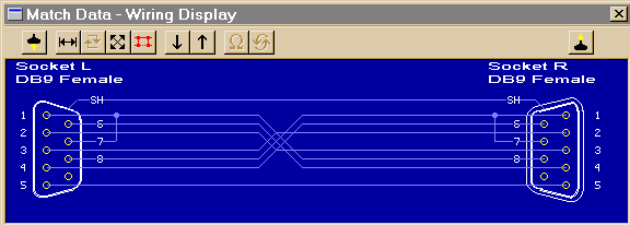
Worked with Kin Chin to get the serial communication to work. After further research, we realized the male to male wiring of the store bought cable was not at all what we needed. Logically, the correct pinout was what we found being referenced on one site:
Cable connection.gif
I soldered a cable per that pinout and - it worked! Kin Chin and I worked on a simple protocol for the dual H-bridge setup and added that to the micro program.

November 30, 2011 (8 hours):
Got some cables from Dr. Swabey and crimped ends on for connecting the micro to the motor driver circuit. Bought the following for building an H-bridge:
4 x IRF9630
4 x IRF630
4 x 4N28

Spent a while testing an H-bridge configuration. I kept having problems that didn't seem to make any sense - at one point forward would work and backward wouldn't when the port pins were definitely switching the opto-isolators. The reverse voltage was actually .1V. Kin Chin came and we probed more around the circuit and started switching components out. We narrowed the problem down to the 4N28 which, after further inspection of the data sheet, I realized that I was probably frying them with too much current from the battery. We switched the configuration to use TIP120's instead of the 4N28's and the circuit finally worked for forward and backward. We updated the code on the micro to reflect changes in the control.

I added a startup script to the Pandaboard that runs 'sudo chmod 777 /dev/ttyO2' when the board boots. I will soon add the command 'sudo webcam /etc/webcam.conf &' so that the webcam is initialized on startup. If I have time and can figure it out, I will add commands so the board emails me its IP address when it boots - however I am unsure of how this would work.

Dec 1, 2011 (5.5 hours):
Attended video conference with Hong Kong. Most of the discussion revolved around how the system diagram has changed from the intial proposal and what we can do to allow for more integration between the teams. The goal by next thursday is to update the Rhea discussions page with our ideas for a system diagram including specifics and also continue developing the protocol.
Went to lab after the video conference to continue working on the project. Since I had gotten the H bridge circuit working, I condensed the layout and put two on one breadboard to allow it to fit in the tank. We worked on fitting the pandaboard, micro, dual H-bridge setup, and all wiring into the tank. It took a while and most of the mounting is rigged up, but it is all fairly secure and no metal on metal contact can occur. For this semester, the tank will be plugged into the wall as we do not have time to worry about battery power for all components at this point. We tested it out and only one tread was moving. After further inspection, I found a wire in the wrong place on one of the H-bridge circuits. After moving it, both treads worked. The tank can move forward and backward as well as turn right and left.

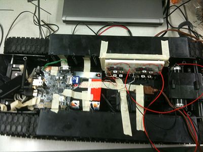
Here is a picture of the tank internals:

Tank internals.JPG


On the left you can see the Pandaboard. Underneath that is the micro - both are mounted with cardboard and masking tape. The transformer is for the Pandaboard. The micro gets power from the Pandaboard through a USB port. On the breadboard you can see both H-bridge circuits which the micro port pins and motors are connected to. The battery for the motors is in its compartment underneath. The green wiring coming out of the Pandaboard comprises a custom wired serial cable that we made according to the previous serial cable diagram.

Cannot seem to get the webcam working consistently. Added it to the startup script; however, when you unplug the monitor it stops working completely. I won't worry about the webcam right now. If need be (in the near future), a webcam can be attached to a computer near the tank. We need to acquire one like Dr. J's as it works much better than the ones we are working with.

Update: Figured out how to get the camera working at least for demo purposes: SSH into the server after figuring out the IP address and kill the camera process and restart it. Commands:
>ps aux | less | grep webcam
>kill "proc#"
>sudo chmod 777 /dev/video0
>sudo webcam /etc/webcam.conf &

Dec 2, 2011 (2 hours):
Setup the tank in preparation for the demo. Demoed the tank for Dr. J, Dr. Swabey, and Dr. Krogmeier.

Here is the tank in action:
Tank Demo

Here are some obvious problems that will need to be addressed:
1. Gearbox is shot, or some other problem with tank drive.
2. Barrel connector on the Pandaboard is not the right size causing disconnection when bumped.
3. We need a more stable connection to the pandaboard wirelessly
4. Need to figure out power requirements for our hardware to find a battery.


WEEK SUMMARY:

Accomplishments: Tank control successfully demonstrated!
Weekly Work Total: 29.5 hours
Project Work Total: 97.4 hours


Week of Dec. 5

December 6, 2011 (1.5 hours):
Met with group to discuss protocol and system architecture as well as outline for the final report. We decided that there isn't much we can do to change the overall architecture without changing the current vehicle setup.

December 7, 2011 (45 minutes):
Met with Dr. J to discuss the final report - decided it needs to be a combination of VIP final report and 477 proposal in layout.

1. Title

2. Executive Summary

3. Outcomes

  • Prototyping (Scott, Kin Chin, Chris)
    • Proof of concept
    • Practice technologies
    • Demo ARM MCU control
    • Demo remote control of ARM
  • Proposal for ECE 477 (Jason, Matt)
    • Requirements
    • Components
    • Architecture
    • Protocol
    • Vehicle Platform
  • Collaboration with HKUST (Michael)

4. Research and prototyping (Scott, Kin Chin, Chris)

  • Requirements
  • Components
  • Architecture
  • Vehicle Platform
  • Prototyping Results

5. Proposed ECE 477 Project (Jason, Matt)

  • Requirements
    • Features
      • Physical
      • Environment
    • Expectations regarding integration
  • Components
  • Architecture
  • Protocol
  • Vehicle Platform

6. Conclusions (Michael)

  • Summary of accomplishments
  • Collaboration Summary
    • Communication methods
    • Joint decisions

7. Appendix

  • Code
  • Data
  • Pictures

December 8, 2011 (1.5 hours):
Attended video conference. However, no HKUST members showed up. Instead, we discussed the overall system architecture and came up with a new plan to allow for more integration. Also delegated parts of final report.

December 9, 2011 (2 hours):
Looked into H-brides. The L298 looks like a great chip and is widely used, but it is designed to work on the 5v logic level. We will either need to step up the voltage or figure out if the micro can work on the 5v level - currently at 3.3v. Stepping up the voltage would not be difficult.

Attended weekly meeting where we went over Hong Kong's idea for a system architecture - similar to what I had proposed at a previous meeting with a central server that directs vehicle control to the appropriate vehicle. It will add some latency but will make the project make a lot more sense and easily extensible.


WEEK SUMMARY:

Accomplishments: Getting very close to an agreement on system architecture that is logical
Weekly Work Total: 5.7 hours
Project Work Total: 103.1 hours


Back to Design Notebooks

Alumni Liaison

To all math majors: "Mathematics is a wonderfully rich subject."

Dr. Paul Garrett