Characteristic Analysis of a Simple Distortion Pedal (incomplete yet)
by Haoyu Chen
Contents
[hide]Background
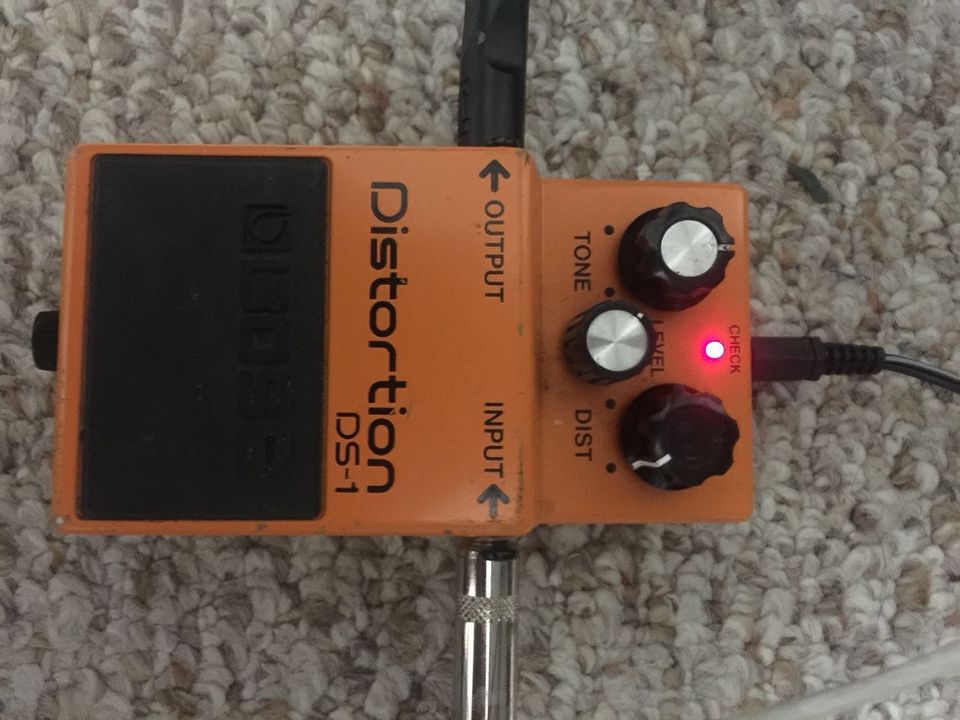
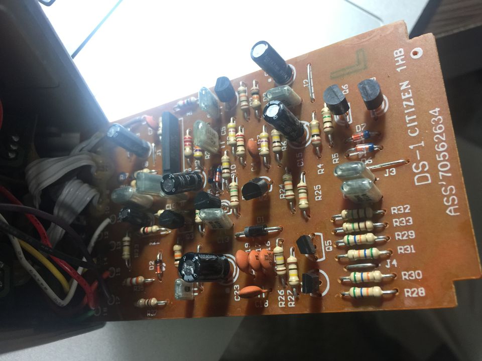
One day when I was playing with my DS-1 Distortion Pedal, I noticed that the circuit inside it was quite simple (it only consists of RC circuits, diodes, and op-amps), and I got curious about how they works in processing the music signal from a electric guitar. So I looked up wikipedia on how distortion works as well as a website that teaches you to "build your own DS-1 pedal."
Overview
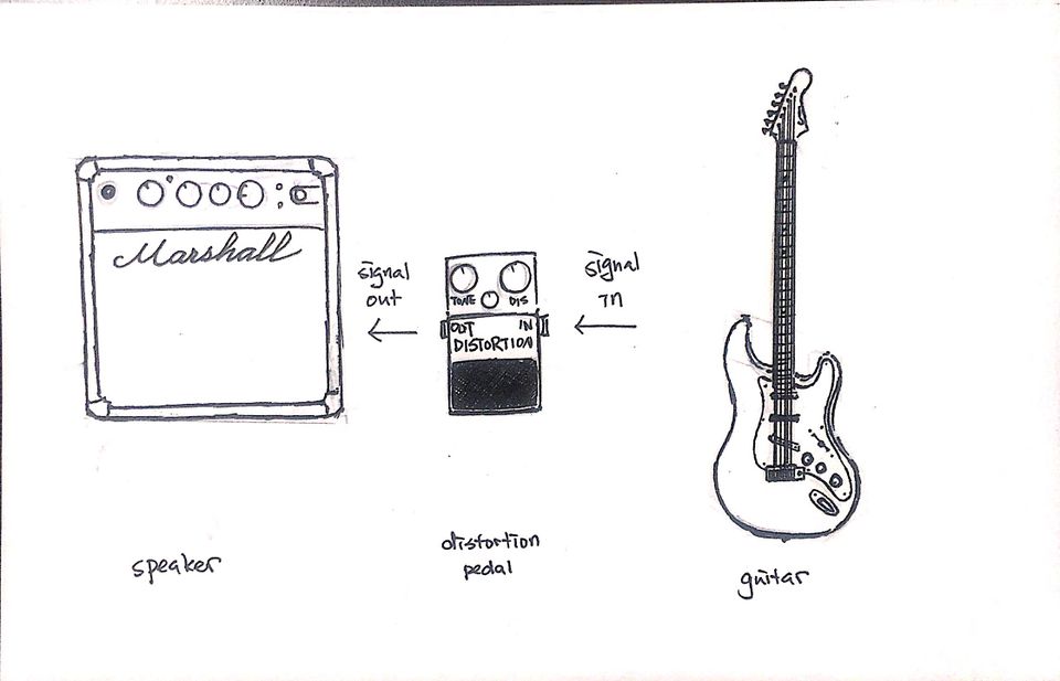
Usually, the music signal played on an electric guitar is not directly played out by speaker, instead, the signal goes through one or more pedals to create different distortion to the signal. In this case, I am using a BOSS DS-1 distortion pedal. The DS-1 distortion pedal's circuit consists of 5 main parts:
Input Buffer → Transistor Booster → Gain & Distortion → Tone → Output Buffer
And the main parts that's making changes to the music signal are the Gain & Distortion part and the Tone part.
Distortion
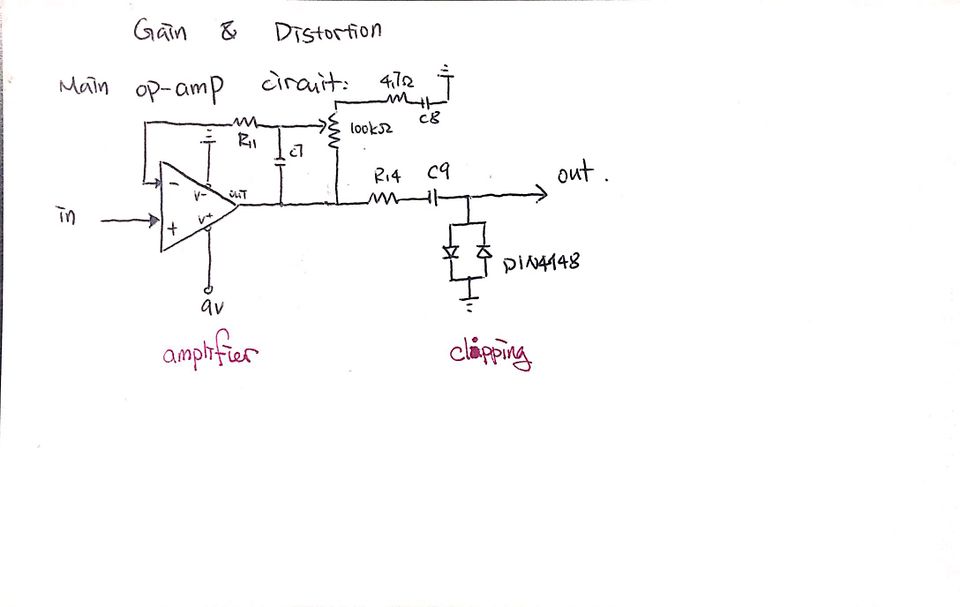
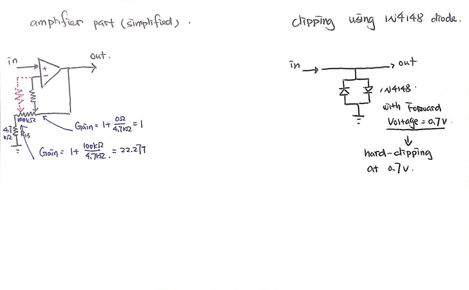
The distortion circuit actually has two part: Gain and Clipping:
↑a simplified circuit for Gain and Clipping respectively
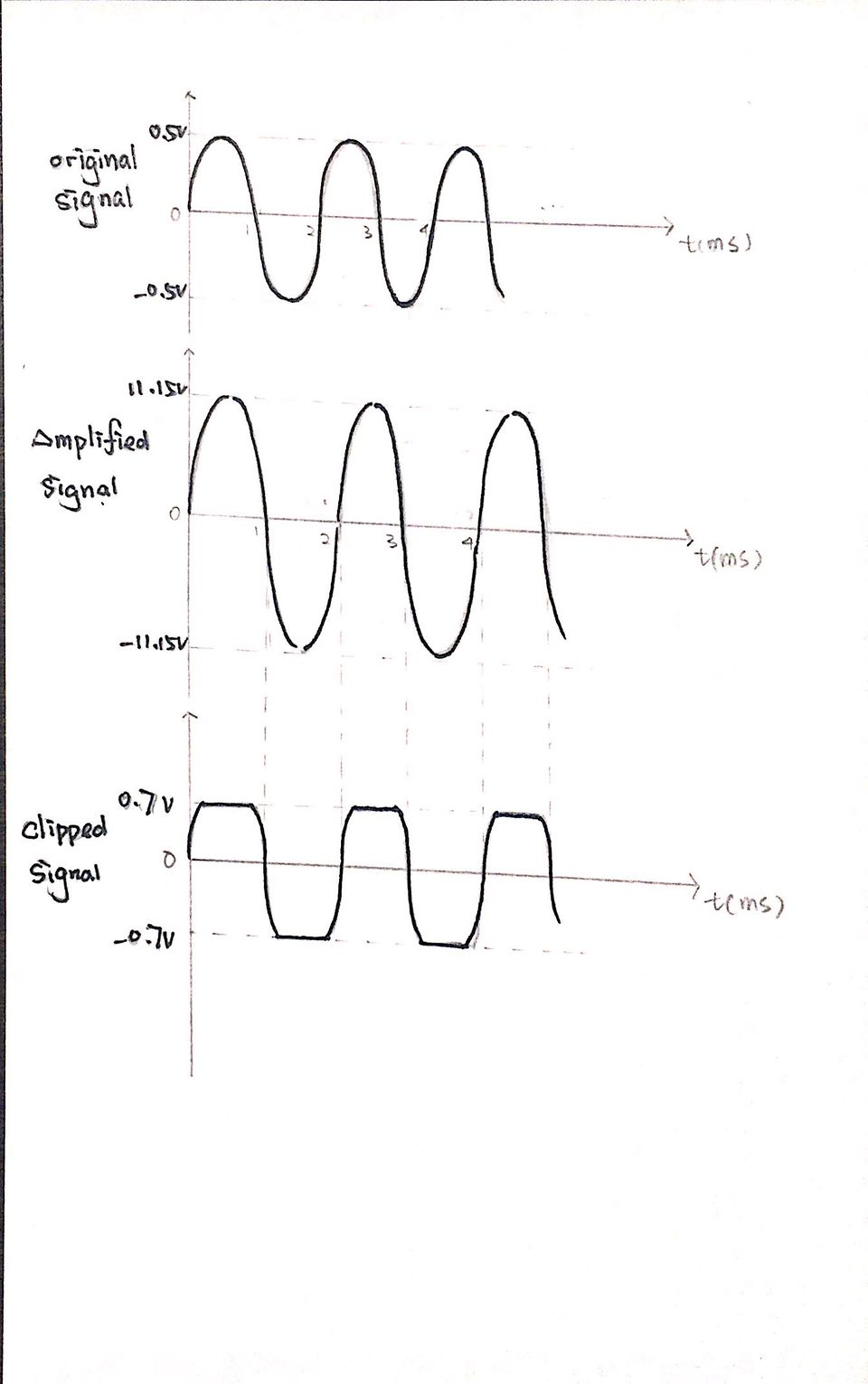
The Gain part is made of an op-amp with a potentiometer, which allows the user to change the Gain factor by turning the potentiometer. Then, after the signal is amplified, this pair of 1N4148 diodes with Vf = 0.7V would cut off any signal part with amplitude larger than 0.7V, thus creating a "hard-clipped" signal. (Clipping) The Clipped signal sounds differently because of the new shape of the signal, and the sound could be "gritty" or "fuzzy", which makes is "distorted."
Here is an illustration of a simple example with a sine wave as input signal:
Tone
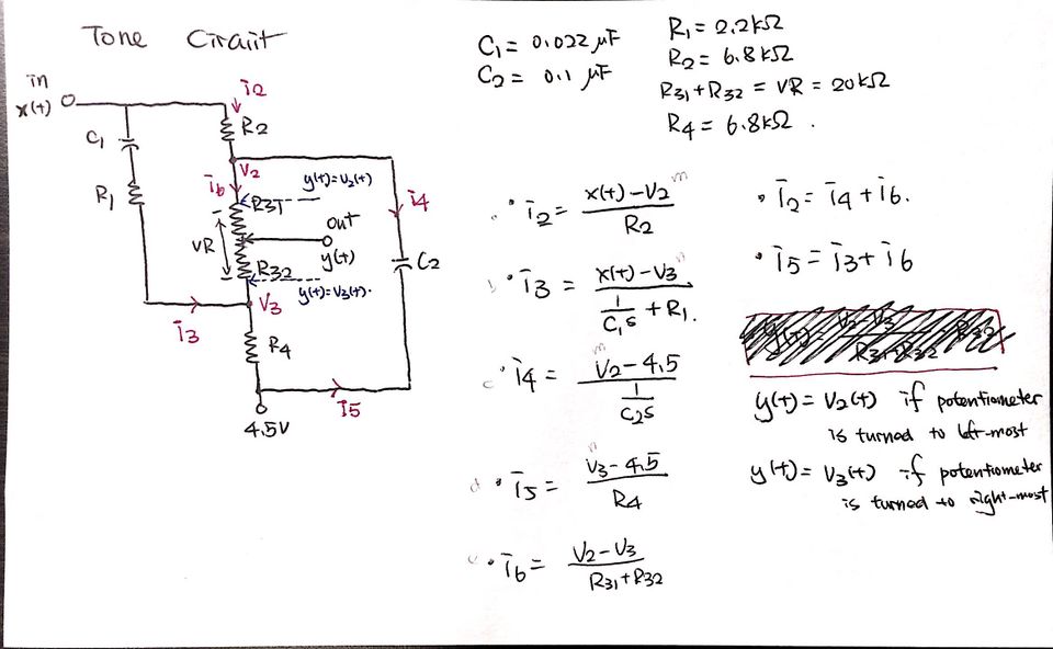
The part of circuit that controls the "Tone" of the output signal looks like this:
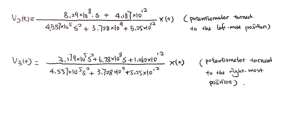
Unable to compute the original transfer functions, I replaced the reference point of 4.5V with 0V, and I assumed that the frequency responses' filter characteristics should remain the same. With calculations done on scratch paper and finalized through WolframAlpha, I was able to attain following transfer functions: (with the Tone button turn to leftmost position and to the rightmost position respectively)
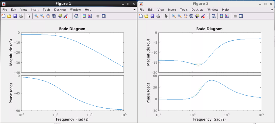
With the help of Matlab, I obtained frequency responses for both transfer function: (with the Tone button turn to leftmost position and to the rightmost position respectively)
As we can see, the leftmost position offers a Low-Pass Filter while the rightmost position offers a High-Pass Filter, which fits the User's Manual description of "Max Bass" and "Max Treble."
Sources
[1] BUILD YOUR OWN DS-1 DISTORTION, http://freestompboxes.org/members/5thumbs/Build%20Your%20Own%20DS-1%20Distortion.pdf
[2] Distortion (music), on Wikipedia, https://en.wikipedia.org/wiki/Distortion_(music)

